A Chain is as Strong as its Average Link: Considering Weld Line Positions Might be a Good Idea

This guest contribution on the Altair Blog is written by Dr. Marcus Stojek, Managing Director at PART Engineering, developers of CONVERSE andS-Life-FKM. PART Engineering is a member of the Altair Partner Alliance.
Weld Line Positions are often an underrated by-product of the filling simulation of plastic components. Why can this be a big mistake?
Essentially two numbers are required to evaluate the load capacity of a component under a given condition. One is the stress (or strain), the other one is the strength which also can be given as stress or strain limit. If necessary, an additional safety factor can be taken into account, which virtually increases the stress or lowers the strength.
The stress in the component is usually determined by a FEM simulation and it is intuitively clear that this stress has a different value at each point of the component. A widespread procedure is therefore to use the contour plot (e.g. von-Mises stress) scaled to the permissible, material-specific maximum value (e.g. stress at yield). If this upper limit is reached or exceeded in the component, the according region is assessed as critical. The same is true for a strain based assessment.
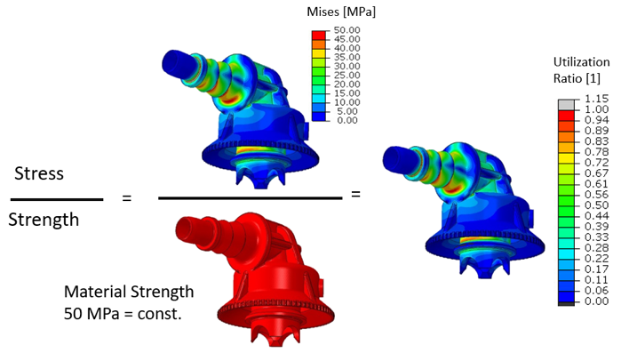
Regardless of the concrete numerical values, this means that the critical point, the position of the first failure, always is identical to the point of highest stress. If a variable utilization ratio is defined as the ratio of stress to strength, then the contour plots of stress and utilization ratio always look identical (fig. 1).
Figure 1 Utilization Ratio With a Homogeneous Material Strength
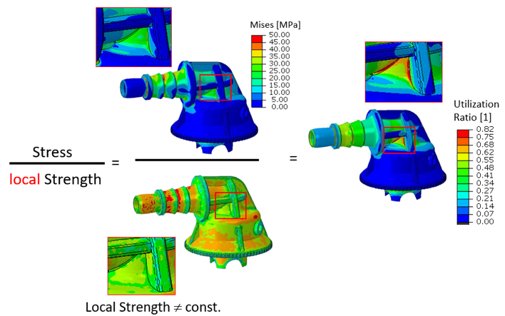
In reality, however, the strength may vary significantly with the position in the component. Influencing factors can be external conditions (temperature, aging), the type of stress (multi-axiality) or material inhomogeneities. Therefore, in order to detect potential failure, the local component strength has to be used instead of an average material strength. Fig 2 shows an example of this approach.
The ratio of stress and strength is the most critical here at a position in the component, which is not conspicuous in the pure stress evaluation. It is critical, because the local strength is significantly lower than the database material strength.
Especially for plastic components such inhomogeneities are almost always present, namely in the form of fiber orientations and weld lines. Weld or flow lines occur in injection molded components wherever two melt fronts meet. Causes are all types of breakthroughs in the component, multiple gating points or complex filling patterns. Depending on the angle, pressure, temperature and especially the flow processes after the weld line formation, the local material strength diminishes perpendicular to the weld line. This applies equally to unfilled and fiber-reinforced plastics. In the fiber-reinforced materials, the unfavorable orientation of the fibers and sometimes a pure matrix boundary layer can increase the effect of reduced strength.
Because the positions of possible weld lines are completely determined by the flow pattern of the melt, these locations are an immanent result of any filling simulation. But while the use of fiber data from filling simulations is becoming more and more common, other valuable information from filling simulation is often ignored. And weld line positions certainly are valuable data.
The weld line strength can vary between 100% and actually 0% of the strength of the homogeneous material. Typical values are 80 to 40%. Sometimes, as a conservative rule of thumb, a reduction factor of (1-ϕ) is applied to the strength of the matrix material (ϕ: fiber weight content). A difference that can account for severe misjudgment in the component evaluation and thus outweighs many other influencing factors... If the weld line is unfavorably positioned.
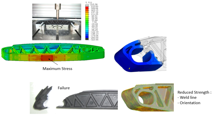
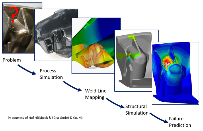
Despite the utmost care, a disregarded weld line can therefore make the result of an FE simulation misleading, both in terms of the permissible loads and in terms of the failure position in the component (fig. 3 and 4).
This is all the more unnecessary as there are several ways to consider the weld line strength at different levels of complexity:
- Visual assignment of the affected component regions and manual evaluation with lump-sum reduction factors. Only applicable for simple geometries and filling patterns.
- The mapping of corresponding element sets from the filling to the structural simulation with blanket reduction factors in the postprocessing. This should be considered for more complex geometries with a significant number of weld lines.
- Assignment of separate material models to weld line regions with corresponding damage models. The weld line strength can be estimated or has to be measured with double-gated tensile bars.
- Prediction of local weld line strength based on process data from the filling simulation. This is an object of research.
Even, if admittedly the prediction of weld line strength can be difficult, the mere consideration of their loacation in an FE-model can reduce the chance of misjudgment significantly. Hence, the mapping of weld lines should be included in any simulation process of plastic components if possible. Especially, because the effort can be close to zero.
CONVERSE by PART Engineering is an easy-to-use, reliable and fast software tool which takes the information provided by an injection molding simulation, transfers it to a downstream mechanical simulation of the component. Amongst other data, weld line positions can be mapped between arbitrary mesh types and are exported as grouped element sets in the particular solver syntax. Whether or not these element sets are used for a specific material assignment is up to the user. Converse can be accessed through the Altair Partner Alliance.


