Applying loads and displacements
Altair SimSolid provides very general methods for applying loads and displacements. They may be applied to any part region and in any arbitrary reference frame. All this is done from one convenient Load/displacement dialog. Read on to find out more.

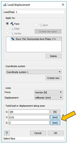
Although not commonly done, a load can be specified in one direction and a displacement in another. On the dialog above, a 100 N load is applied along the local X axis, a 0.01 mm displacement is defined along the local Y axis and the displacement in local Z is fixed at 0 mm. Pretty cool!
A more common application is to use specified zero displacements to define simple supported boundary conditions. Picking vertices and using the common FEA 3-2-1 convention, zero displacement values can be used to remove simple rigid body motion. Other combinations are possible as well. For example, pick a face and specify zero X displacement means that the face will not displace in X but is free to move in X and Z.
Finally, don’t like the default units? These can be changed using the Units pull-down menus. The values will adjust on the fly.
Pick where to apply
To begin, open the dialog and specify the region to apply the load or displacement to. Four entities are possible: a part face, edge, vertex or the more general spot. Faces, edges and vertices are typical of other applications, but spots are not. In Altair SimSolid, almost any shape region can be defined as a load application location. Some possible shapes are seen below but even more are possible. Base shapes can degenerate, so lines, curved edges, even general points are possible. For more information on creating spots see this previous posting.
Pick the reference frame
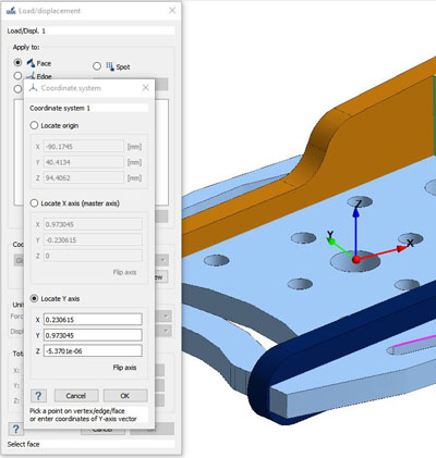
By default, all loads and displacements are applied in the global XYZ coordinates system, but local frames are possible. To define a local coordinate system, pick the “Create New” button, then follow the prompts to locate the origin and axes orientation. Note that reference faces, edges or vertices can be picked on the model. In addition, the reference frame origin may be selected and dragged. Fine tune the value with the text boxes as required and select OK to complete the definition.
Pick load or displacement
Now all that is left is to define the value to apply. Note that both loads and displacements may be defined using this one form. By default, Altair SimSolid assumes a load. To switch to displacement, simply pick the unit box at the end of the value field as shown.Although not commonly done, a load can be specified in one direction and a displacement in another. On the dialog above, a 100 N load is applied along the local X axis, a 0.01 mm displacement is defined along the local Y axis and the displacement in local Z is fixed at 0 mm. Pretty cool!
A more common application is to use specified zero displacements to define simple supported boundary conditions. Picking vertices and using the common FEA 3-2-1 convention, zero displacement values can be used to remove simple rigid body motion. Other combinations are possible as well. For example, pick a face and specify zero X displacement means that the face will not displace in X but is free to move in X and Z.
Finally, don’t like the default units? These can be changed using the Units pull-down menus. The values will adjust on the fly.