Digital Debunking: An Engineer Examines the Weapons of ‘Game of Thrones’
Medieval Myth Busting with Engineering Simulation
As an avid of fan of HBO's uber-popular medieval fantasy series Game of Thrones, I’ve often been curious about the feasibility of the weaponry we see in the show’s epic battle scenes. I took a particular interest in the massive trebuchets, a fancy name for a catapult, used in many of the show’s siege battles. This powerful catapult uses a swinging arm and counterweight to hurl projectiles over and through fortified castle walls and at battalions of oncoming soldiers. Of course, only an engineer like me would be able to suspend their disbelief for dragons and ice zombies while obsessing over the plausibility of a trebuchet But still I wondered, would the computer-generated mechanisms depicted on screen stand up to the laws of physics?The best way to understand how the trebuchet would behave is to put it to the test. I used Altair InspireTM Motion to create a simulation model, define the design constraints and performance goals, then simulate the catapult in action. We can then transfer the motion loads onto the structure to assess the feasibility of the initial design and even optimize the geometry to create a stronger and better performing final design.
One of the advantages of working with Altair Inspire is how it lets users build concepts quickly and easily simulate multiple iterations. There’s little risk in experimenting … in fact we recommend it since this iterative approach is especially helpful for businesses to get to market quicker and mitigate risks. In my case as a geeky application engineer and super-user, Inspire is ideal in helping me satisfy my recreational curiosities by building a few virtual models and putting them to the test.
So, back to Game of Thrones… I came across this blog that addresses some feasibility issues with the trebuchets shown in the show’s siege of Meereen. Clearly, I’m not the only one thinking about these things. https://scottmanning.com/content/3-problems-with-this-game-of-thrones-trebuchet/
The author lays out a few basic issues: 1. The counterweight would be insufficient 2. There is not enough structure to support the required counterweight 3. How would you load the projectile? 4. How would you light the projectile?
Items three and four are very obvious and don’t require analysis to prove or disprove. I wanted to look at the counterweight mass and structure. Rather than trying to recreate the structure exactly, I just wanted to know if its feasible to build a wooden structure that can handle the required counterweight and dynamic loading. The kinematics are set up to mimic the CGI trebuchet and I ran a few studies varying counterweight mass to determine the ideal weight for this design and payload mass. From there I used motion-generated loads and topology optimization to see what kind of structure would be needed to survive the predicted loading.
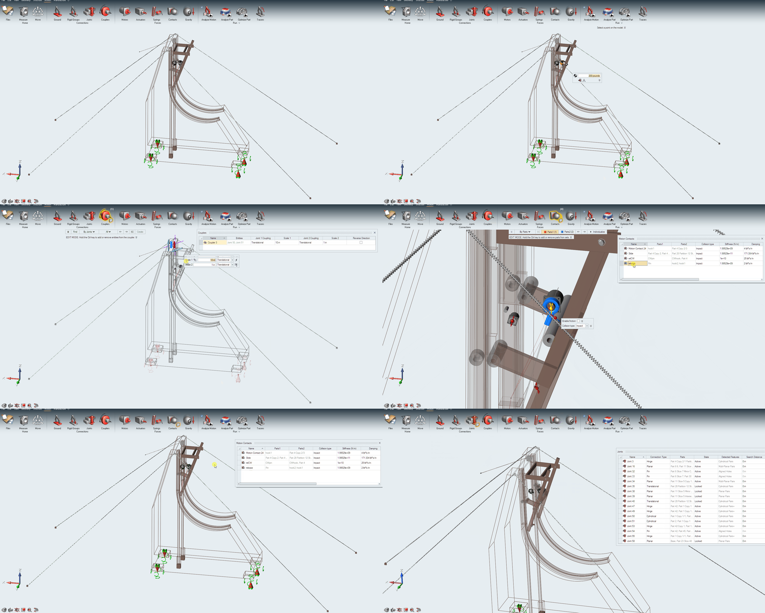
I settled on a 200lbm payload mass after doing a little online research-about the mass of an ACME anvil. Since this is a fantasy trebuchet, that seems about right. After a few studies, I selected a counterweight mass. I used the 10,000lb mass given a 50 percent increase or more in loading isn’t worth the effort for an extra 50 meters of distance.
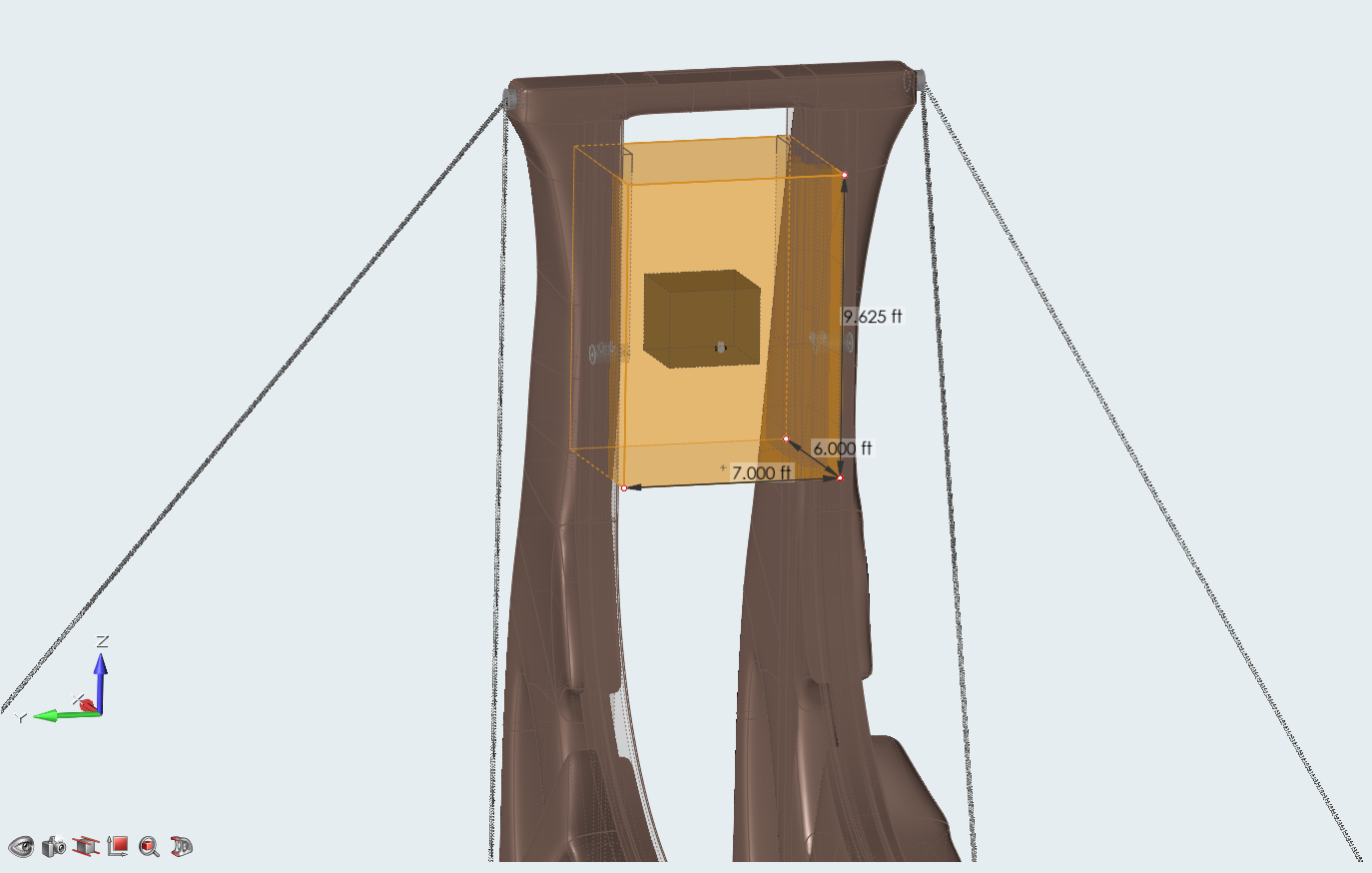
The predicted range is around 350m, which is more than a bow and arrow, and with that mass would certainly pack a punch. In the picture below, the darker block is an iron counterweight and the larger brown block is a wooden counterweight. In the Game of Thrones trebuchet, we don’t see anything that heavy.
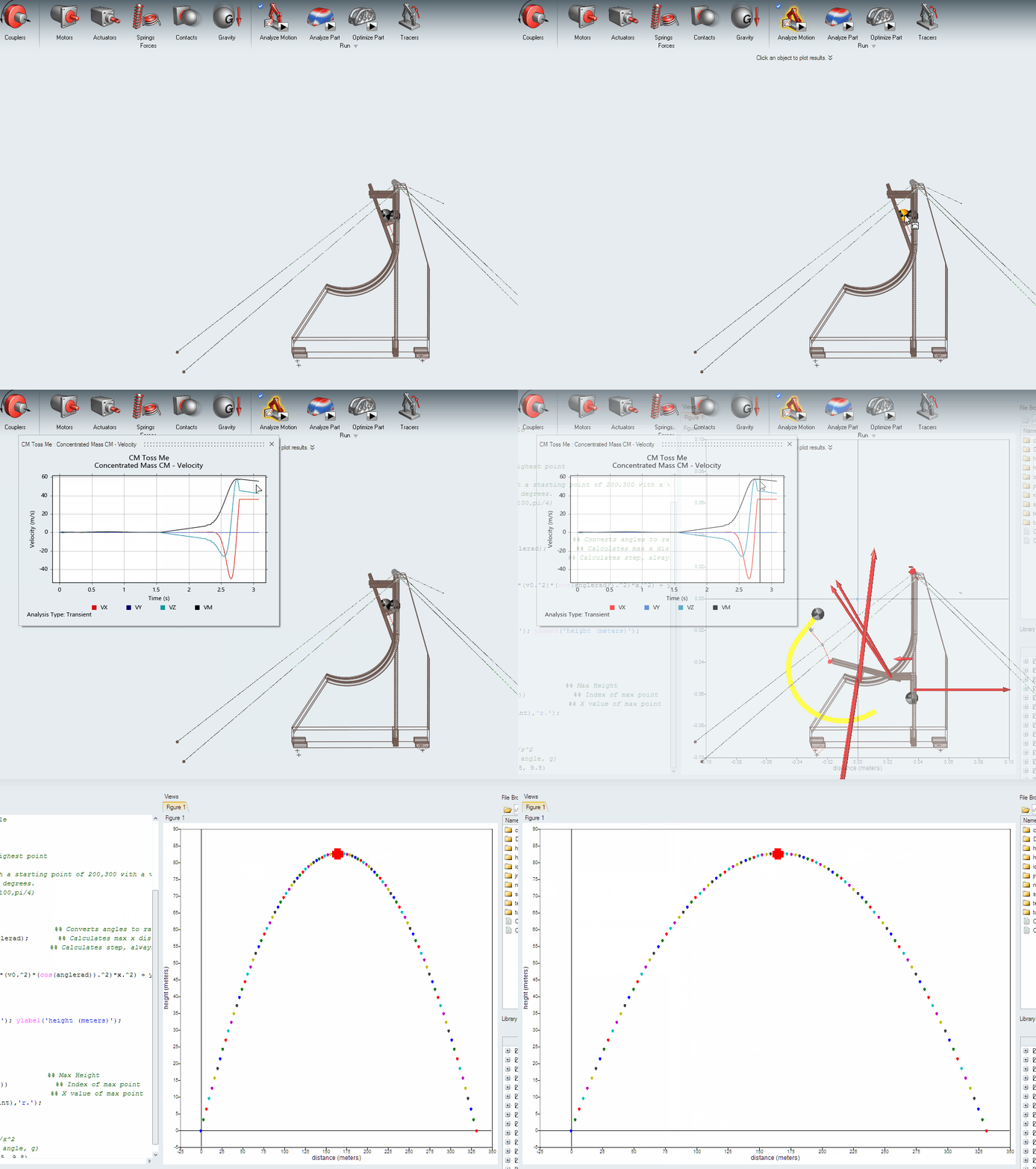
I checked the release velocity of the projectile and ran a quick script in Altair Compose to generate a projectile motion plot.
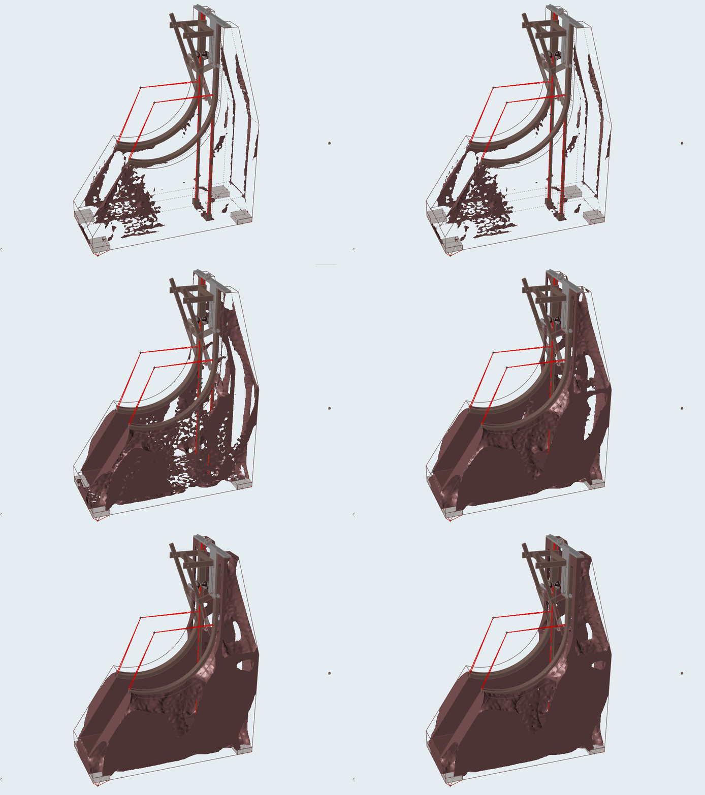
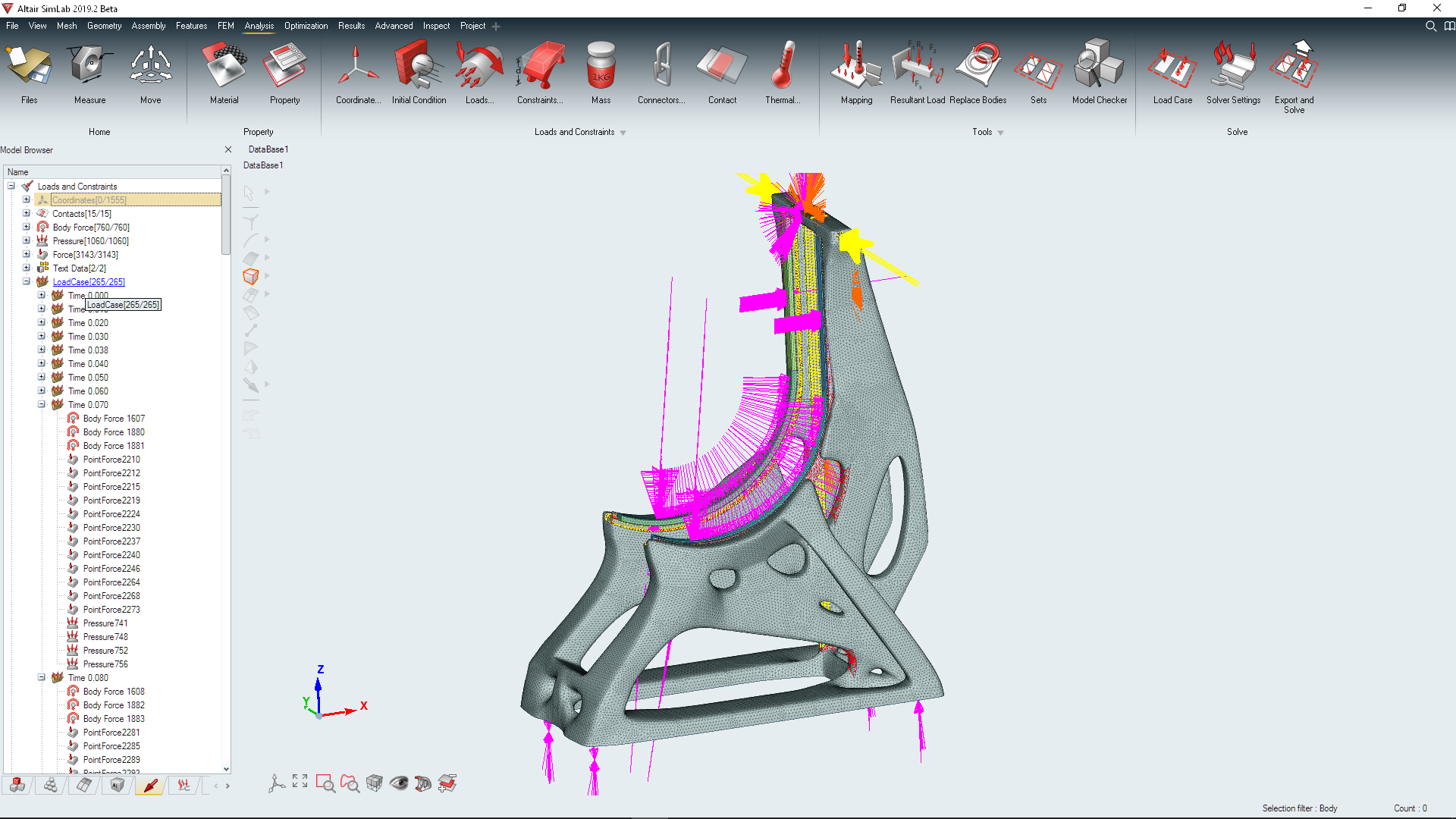
The beauty of working with Inspire Motion is that loading is seamlessly transferred to structural analysis and optimization. I directly applied the loads to two optimization studies.
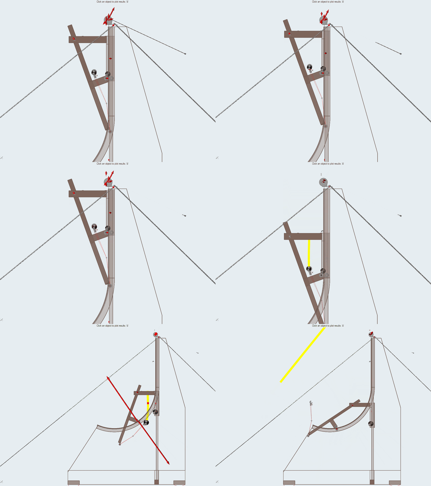
In this animated motion study, the counterweight is lifted with a 10 to 1 reduction coupler at the top. This generated vertical and lateral loads on the frame from the lifting process. Then, the counterweight is released and finally, the projectile is unleashed to wreak havoc.
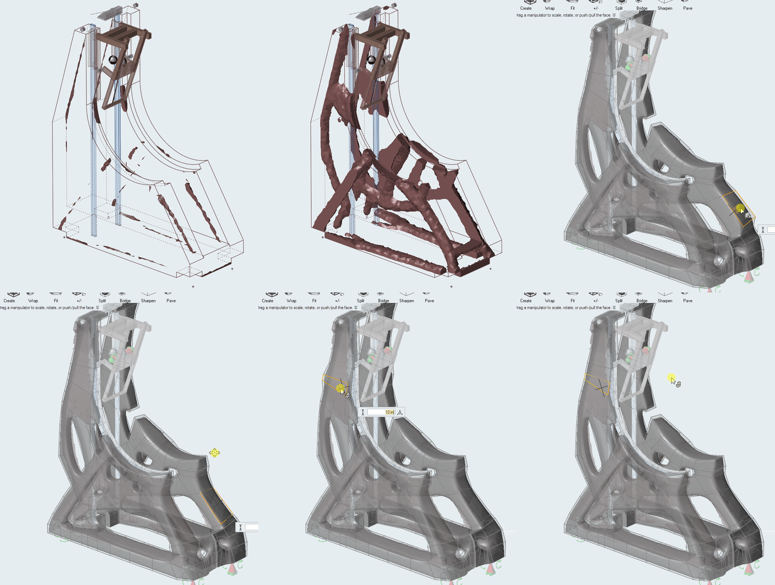
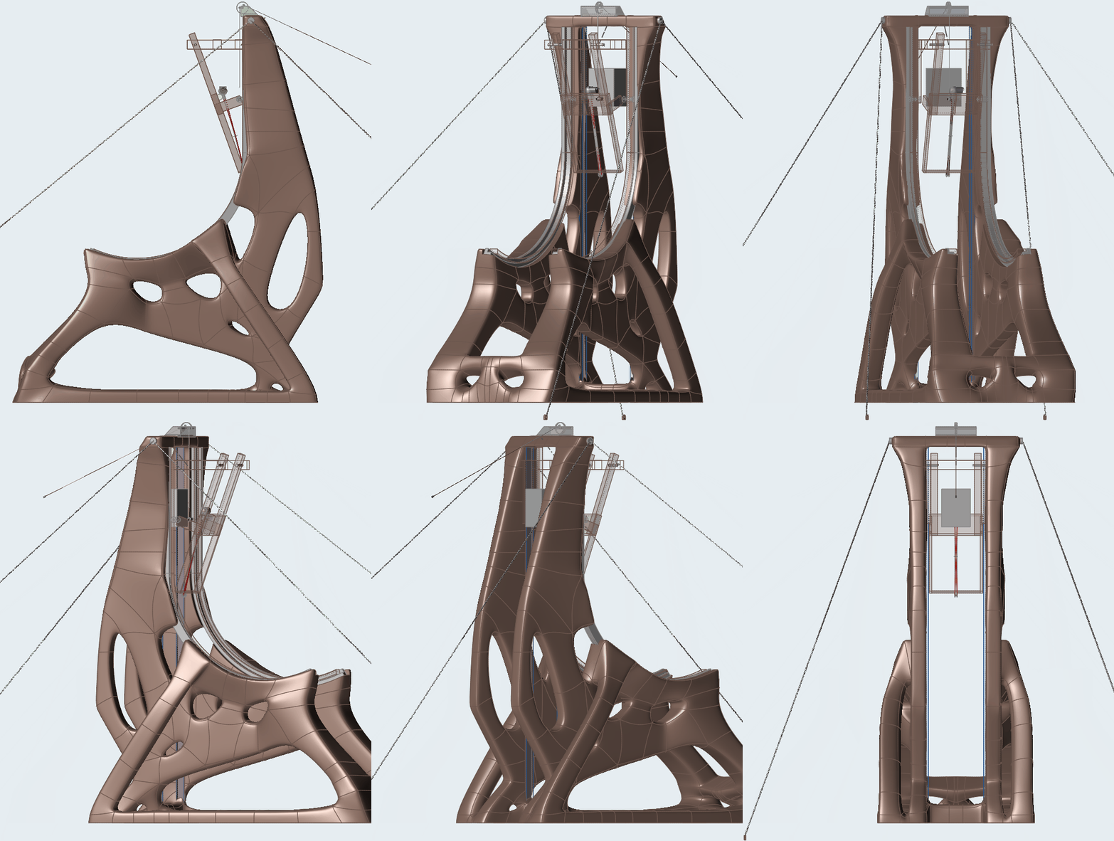 After running the optimization, the optimized shape from the Minimize Mass study was wrapped in Inspire using Polynurbs.
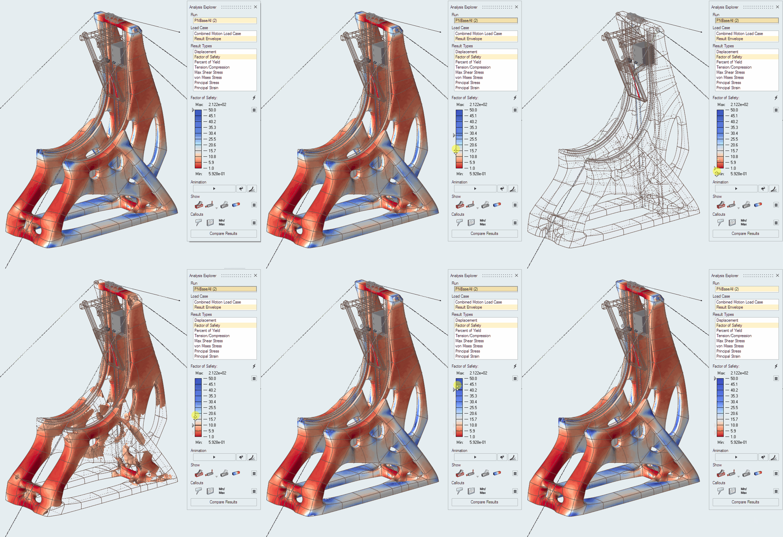
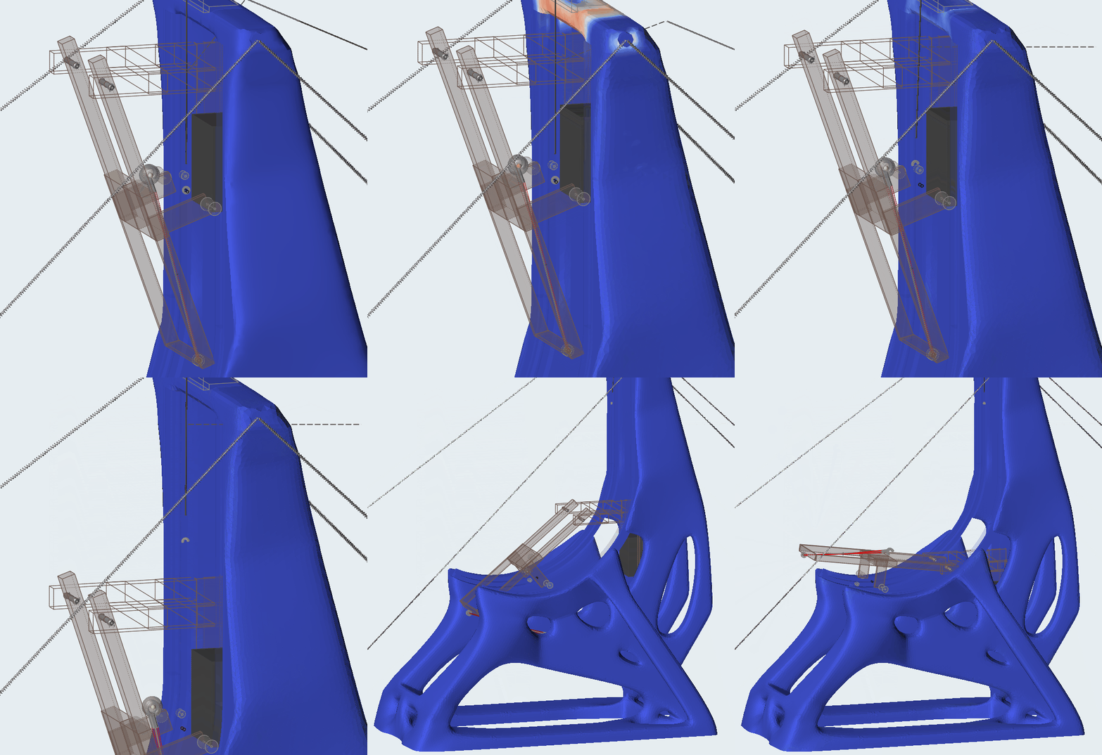 Analysis of Minimize Mass Design Showing Factor of Safety contour for a 10000lb counterweight and 200lb projectile.
Is This Design Feasible?
So, after all this analysis, what have we determined? The exact trebuchet from the show isn’t feasible as shown. It would absolutely require a larger counterweight. However, with a little more engineering and a LOT more wood, it would be doable. Regarding lighting of the projectile, we can solve that problem in another blog post.

Crawl, Walk, Run
When creating simulation models, I recommend a crawl, walk, run approach. Start by defining the goal of the simulation and let that determine the level of detail needed in the model. You can start with a simple stick figure like I did in this study in order to get simple design feasibility results. If you need more detailed results, additional complexity can be added to the model, such as actuators, contact sets, and stress analysis driven from the motion loads.
Want to try this for yourself?
If you’re not an Inspire user already, you can sign up for a 15-day trial.
I’ve also created these tutorial videos which walk you through the initial stages of the process for setting up your own trebuchet experiment.
- Tutorial Video 1: Ground, Rigid Groups, Joints and Contacts and Results
- Tutorial Video 2: Actuators, Motors and Springs


