Combining 2D and 3D Simulation

We must often strike the right balance between the computational time and accuracy of our simulation. Simplification/removal of unimportant CAD features, locally refined mesh, and usage of equivalent elements are some proven methodologies to reduce the calculation time. If the product geometry and operating conditions are conducive, combining 2D and 3D simulations is another very effective method to reduce the calculation time without losing out on the accuracy. Below is an imaginary conversation between two brothers from the simulation community who converse about this method.
2Dee and 3Dee personify 2 dimensional and 3 dimensional elements respectively from now onwards.
2Dee, the younger one, feels sad that people don’t give him the respect which he rightly deserves. So, he speaks his mind to his elder brother 3Dee. Being the responsible elder sibling, 3Dee patiently listens and then takes 2Dee on the path down the memory lane. The brothers discuss their union in the past when they had joined hands for solving a multistage automatic cold forging process. After the discussion, 2Dee feels very happy and cheerful again.
So, what did 3Dee say? Let’s check out.
2Dee: I don’t know why, but people are constantly looking down on me. I feel sad.
3Dee: I feel sorry for you buddy.
2Dee: They always rely on you too much even if I can give them reliable results.
3Dee: I am sure that you are simpler and much quicker than me. Elaborate your point in detail.
2Dee: Let’s take quadrilateral elements from my clan and tetrahedral elements from yours just for the sake of comparison. When an axisymmetric forging process is analyzed using quadrilateral elements, there is very little possibility [1] for intervention of numerical uncertainties. This means, a stable solution can be obtained economically compared to the tetrahedral elements. In other words, if the same problem is solved using two and three-dimensional approaches, and if the solution differs slightly, then the two-dimensional approach using quadrilateral elements is more accurate.
3Dee: You have a point. The differences in the solution arise because of the different theoretical backgrounds that we are based upon. There can never be a one-strategy-fits-all approach. The element selection depends on the specific problem and its conditions. Since three-dimensional approaches consume more time right from preparing the input geometry to obtaining the solution, the simulation engineer must take the right decision. Having said that, I would like to remind you about this journal paper [2] where M.C. Lee et.al used the synergies of both 2D and 3D approaches.
2Dee: Was it about analyzing the sequence of a multistage automatic cold-forging process of a fastener using AFDEX? (2Dee’s eyes light up). It was way back in 2009 If I am not wrong.
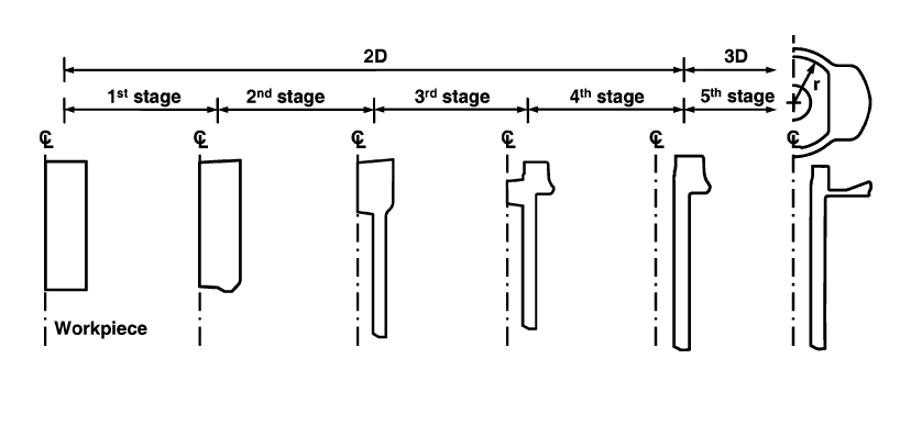
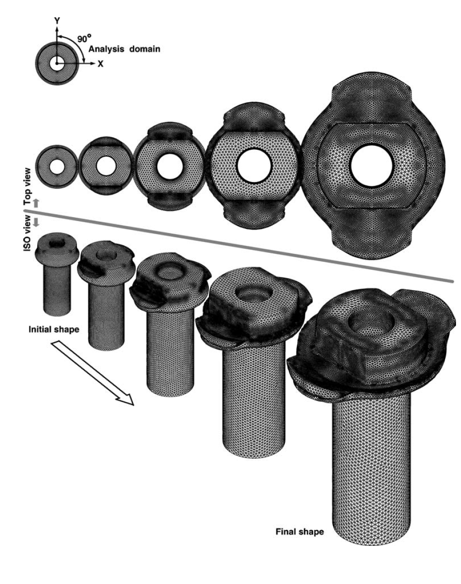
3Dee: Yes, you are right. It was a 5-stage cold forging process consisting of four axisymmetric stages and one non-axisymmetric stage. The sequence also had a piercing and overlapping process making it representative of multi stage automatic forging sequences. The forging simulator AFDEX was used. Does Figure 1 look familiar to you?
2Dee: Oh yes! Those were great times. Weren’t they?
3Dee: Yes, undoubtedly. Quadrilateral elements for 2D approaches (first four axisymmetric stages) and tetrahedral MINI-elements for 3D approach (final stage, non-axisymmetric) were employed. The workpiece was pierced during the fourth stage and headed during the final stage. The workpiece flash had overlapped during heading process and this was removed by an additional trimming process which was not included in this part of the study. The axisymmetric simulations were carried out with AFDEX 2D for the first 4 stages. For the final stage, one fourth of the geometry was selected employing two planes of symmetry and then simulated using AFDEX 3D. The number of tetrahedral elements were around 80,000 and the process conditions were Friction factor: 0.1
Velocity of upper die: -1 mm/s
2Dee: Could you show some pictures and elaborate on the meshing strategy?
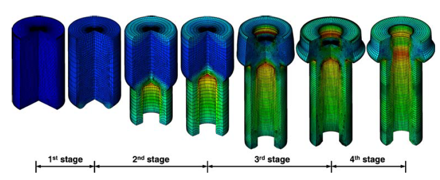
3Dee: Sure. Figures 2 and 3 shows the 3D view of the effective strain contours obtained from the 2D simulations for the first four stages.
 Figure 2: Effective strain contours in the first four stages (2D simulation results displayed in 3D view)
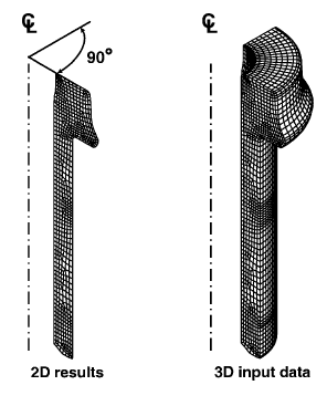
3Dee: The 2D geometry from the fourth stage was rotated to generate the hexahedral elements as shown in Figure 4. The state variables of the hexahedral elements were calculated, and the hexahedral mesh was then automatically remeshed into a tetrahedral mesh system which acted as an input to the final and fifth stage of the process.
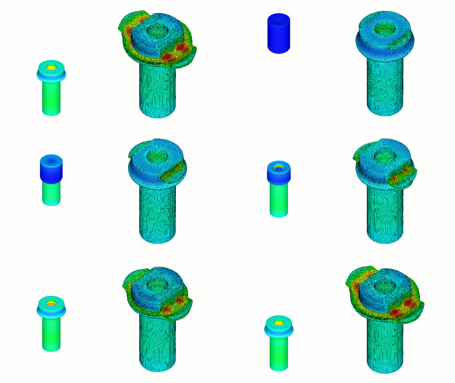
The simulation was continued by using AFDEX 3D. The result animations are presented in Figure 5. and Figure 6 illustrates the excellent quality of mesh as well as the overlapped flash.
2Dee: Thank you very much for reminding me of this worthy example. I feel much better now. Thanks to the intelligent mesh generation technique, the combined 2D and 3D methodology paved way for a precise and accurate simulation of the multistage automatic cold-forging process.
3Dee: I also felt happy reminiscing on our good memories. We all have our own merits and demerits. It is up to our master, the simulation engineer, who is reading this article, to decide wisely and bring the best out of us.
2Dee: Can’t agree more. Have a great (computationally cheaper) day. Bye.
Endnote: After this discussion, 2Dee and 3Dee lived happily ever after.
This guest contribution is written by Renganathan Sekar, M.Sc., researcher at MFRC, the developers of the intelligent metal forming simulation software AFDEX which is available through the Altair Partner Alliance.
References:
[1] M.S. Joun, 2013, Forging Simulation (In Korean), Jinsaem Media
[2] M.C. Lee, S.H. Chung, M.S. Joun, “Automatic and precise simulation of multistage automatic cold-forging processes by combined analyses of two- and three-dimensional approaches”, Int J Adv Manuf Technol (2009), Vol. 41, Pages 1-7
2Dee and 3Dee personify 2 dimensional and 3 dimensional elements respectively from now onwards.
2Dee, the younger one, feels sad that people don’t give him the respect which he rightly deserves. So, he speaks his mind to his elder brother 3Dee. Being the responsible elder sibling, 3Dee patiently listens and then takes 2Dee on the path down the memory lane. The brothers discuss their union in the past when they had joined hands for solving a multistage automatic cold forging process. After the discussion, 2Dee feels very happy and cheerful again.
So, what did 3Dee say? Let’s check out.
2Dee: I don’t know why, but people are constantly looking down on me. I feel sad.
3Dee: I feel sorry for you buddy.
2Dee: They always rely on you too much even if I can give them reliable results.
3Dee: I am sure that you are simpler and much quicker than me. Elaborate your point in detail.
2Dee: Let’s take quadrilateral elements from my clan and tetrahedral elements from yours just for the sake of comparison. When an axisymmetric forging process is analyzed using quadrilateral elements, there is very little possibility [1] for intervention of numerical uncertainties. This means, a stable solution can be obtained economically compared to the tetrahedral elements. In other words, if the same problem is solved using two and three-dimensional approaches, and if the solution differs slightly, then the two-dimensional approach using quadrilateral elements is more accurate.
3Dee: You have a point. The differences in the solution arise because of the different theoretical backgrounds that we are based upon. There can never be a one-strategy-fits-all approach. The element selection depends on the specific problem and its conditions. Since three-dimensional approaches consume more time right from preparing the input geometry to obtaining the solution, the simulation engineer must take the right decision. Having said that, I would like to remind you about this journal paper [2] where M.C. Lee et.al used the synergies of both 2D and 3D approaches.
2Dee: Was it about analyzing the sequence of a multistage automatic cold-forging process of a fastener using AFDEX? (2Dee’s eyes light up). It was way back in 2009 If I am not wrong.
3Dee: Yes, you are right. It was a 5-stage cold forging process consisting of four axisymmetric stages and one non-axisymmetric stage. The sequence also had a piercing and overlapping process making it representative of multi stage automatic forging sequences. The forging simulator AFDEX was used. Does Figure 1 look familiar to you?
2Dee: Oh yes! Those were great times. Weren’t they?
3Dee: Yes, undoubtedly. Quadrilateral elements for 2D approaches (first four axisymmetric stages) and tetrahedral MINI-elements for 3D approach (final stage, non-axisymmetric) were employed. The workpiece was pierced during the fourth stage and headed during the final stage. The workpiece flash had overlapped during heading process and this was removed by an additional trimming process which was not included in this part of the study. The axisymmetric simulations were carried out with AFDEX 2D for the first 4 stages. For the final stage, one fourth of the geometry was selected employing two planes of symmetry and then simulated using AFDEX 3D. The number of tetrahedral elements were around 80,000 and the process conditions were Friction factor: 0.1
Velocity of upper die: -1 mm/s
2Dee: Could you show some pictures and elaborate on the meshing strategy?
3Dee: Sure. Figures 2 and 3 shows the 3D view of the effective strain contours obtained from the 2D simulations for the first four stages.
 Figure 2: Effective strain contours in the first four stages (2D simulation results displayed in 3D view)
3Dee: The 2D geometry from the fourth stage was rotated to generate the hexahedral elements as shown in Figure 4. The state variables of the hexahedral elements were calculated, and the hexahedral mesh was then automatically remeshed into a tetrahedral mesh system which acted as an input to the final and fifth stage of the process.
The simulation was continued by using AFDEX 3D. The result animations are presented in Figure 5. and Figure 6 illustrates the excellent quality of mesh as well as the overlapped flash.
2Dee: Thank you very much for reminding me of this worthy example. I feel much better now. Thanks to the intelligent mesh generation technique, the combined 2D and 3D methodology paved way for a precise and accurate simulation of the multistage automatic cold-forging process.
3Dee: I also felt happy reminiscing on our good memories. We all have our own merits and demerits. It is up to our master, the simulation engineer, who is reading this article, to decide wisely and bring the best out of us.
2Dee: Can’t agree more. Have a great (computationally cheaper) day. Bye.
Endnote: After this discussion, 2Dee and 3Dee lived happily ever after.
This guest contribution is written by Renganathan Sekar, M.Sc., researcher at MFRC, the developers of the intelligent metal forming simulation software AFDEX which is available through the Altair Partner Alliance.
References:
[1] M.S. Joun, 2013, Forging Simulation (In Korean), Jinsaem Media
[2] M.C. Lee, S.H. Chung, M.S. Joun, “Automatic and precise simulation of multistage automatic cold-forging processes by combined analyses of two- and three-dimensional approaches”, Int J Adv Manuf Technol (2009), Vol. 41, Pages 1-7


