“We’ve achieved significant weight reduction and rigidity strength by optimizing the material characteristics from our design.”
— Kogakuin University Solar Team
In order to draw the maximum performance from the body, it was necessary to optimize the carbon fiber reinforced polymer (CFRP) body and completely reproduce the shape and thickness of the wing for a light-weight and high-rigidity body. Altair HyperWorks
was integral to achieving this.
In addition to assisting the team to perform a technology exchange, Altair HyperWorks was extremely effective as a communication tool in researching composite materials under the guidance of a cooperative company.
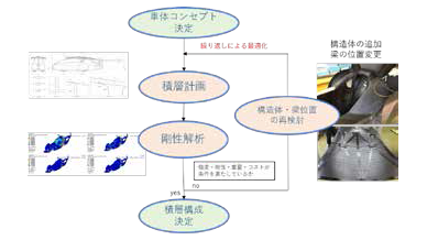
CFRP body structure and lamination plan
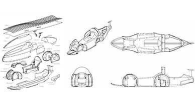
The body has been manufactured by forming carbon fibers using Altair HyperWorks. The type of CFRP (1K, 3K, UD: Uni-Direction, etc.), orientation (90 degree and 45 degree), number of ply, CF, and honeycomb thickness were decided using the layout of the
structure and the beam reinforcement. The structure and lamination plan were decided by a repetitive optimization process (see Fig. 2.).
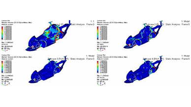
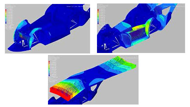
Fig. 4 shows an example of analysis of rigidity in the lamination plan. When load is applied to the two front wheels, the rear wheel house gets deformed in the direction of the opening. This analysis contributed to adding a structure connecting the left
and right wheel house. To keep the weight low while securing the required rigidity, the honeycomb thickness was different at each location of the monocoque. The final weight of only the CFRP parts after manufacturing was approximately 45 kg, indicating
an extremely low weight and high rigidity could be achieved.
Lamination plan of the extremely thin wing
The primary issue in the design of the car body was the lamination of the wing installed at the top serving as a solar cell. In order to examine the configuration of the lightweight, extremely thin, high rigidity wing, structural analysis was performed
using Altair HyperMesh™ and Altair OptiStruct™.
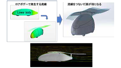
A unique aspect of the design was that the analysis was performed by determining the aerodynamic force and using it as the input load. During the examination of the laminate structure of the wing, the aerodynamic force received by the wing while the solar
car was running at a speed of 130 km/h was clearly identified. The appropriate laminate structure was planned based on the stress and deformation determined from the analysis.
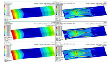
As for the rigidity analysis, models with several patterns based single ply or double ply high-elasticity UD (uni-direction, uni-direction fibers) were used in the reinforcement. They were also used when the difference in the position of the beam was
prepared. The amount of deformation of the wing and location of stress accumulation were checked. Although the double-ply reinforcement beam shown in Fig. 5 had the least displacement, the weight was the highest by 1 kg. Even with this laminate structure,
the force applied when the car ran at a speed of 100 km/h or more was not enough to damage the wing. The laminate structure was re-examined in order to address the deformation suppression required to control the wing vibrations in high-speed regions.
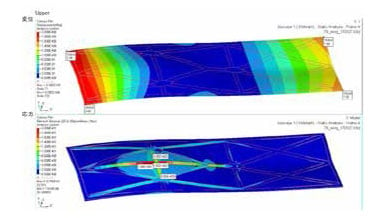
The analysis result shown in Fig. 5, show that stress was accumulated between the left and right stays. This is because when the wing droops down due to the wind, deformation occurs with the stays at the pivot point. Reinforcement was arranged only in
the inclined and short direction, and no reinforcement was inserted to provide support in the longitudinal direction. The study demonstrated that rather than increasing the number of ply, it would be better to insert a reinforcement at the locations
where stress had accumulated and focus on energy distribution to effectively control deformation. If it could be determined that additional reinforcement would be effective in suppressing deformation, it would be possible to lower weight by reducing
the number of ply.
The result of re-analysis performed by inserting a reinforcement in the longitudinal direction at the center of the car is shown in Fig. 6. The high-elasticity UD material reinforcement added in the center exhibits an effect and helps against the deformation
of the wing. Thus, the stress accumulated between the left and right stays and in the inclined UD could be distributed.
For the existing laminate structure, the right could be reduced by as much as 1 kg as compared to the pattern in which a double ply reinforcement UD material was used. Among all the patterns up to this point, this could be the structure with the best
balance between weight and rigidity. Altair HyperMesh and Altair OptiStruct were used for its optimization.
Analysis of fluttering
Fluttering is an unstable phenomenon of self-induced vibrations that occur as a result of elastic vibrations coupling. Aerodynamic force due to bending and torsion results in damage of the structure. For example, the wings of an airplane can be damaged
from amplified dispersion of vibrations. Elastic vibrations occurring in the wing during the running of the car were attenuated by the aerodynamic force, but in high-speed regions, the aerodynamic force boosted the vibrations of the wing to result
in amplified dispersion. This could cause potential damage to the wing.
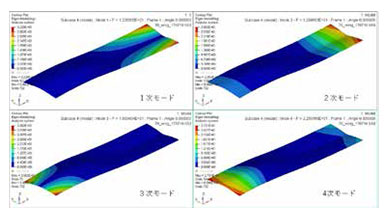
The frequency response (eigenvalue analysis) shown in Fig. 7 was performed to investigate the fluttering. The 1st mode (torsion at the rear end of the wing), the 2nd mode (longitudinal bending at the rear end of the wing), the 3rd mode (torsion at the
front end of the wing), and the 4th mode (longitudinal bending at the front end of the wing) were analyzed.
While the eigenvalues of the 1st and 2nd mode were close to each other, this was due to a resonance phenomenon occurring at a position that was backward of the center of gravity, not believed to result in failure of the wing. Moreover, the eigenvalues
of the 3rd mode and the 4th mode were more than 20 percent apart, not occurring at the same time. This indicated that the resonance phenomenon would occur more or less frequently at the backward position, but an unstable dispersion would not occur.
By performing this analysis, it was possible to determine design such that the deformation forward of the center of gravity would not get dispersed. During testing when the car was made to run, the result was almost the same as the analysis result.
Proof of safety
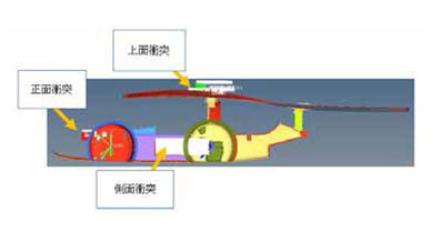
Ensuring the driver’s safety was of utmost priority. Although reinforcement was performed by using a UD material in the laminate of the wing by considering the driver seat and the wheel house as a part of the structure, the structure could be contained
in the minimum space while securing high rigidity. By defining the space for protecting the driver about the structure of the monocoque frame as the passenger cell, the design made it possible prevent the entry of the deformation during collision
into the driver space. (Fig 9)
During side collisions, the left/right wheelhouse protects against the deformation of the monocoque sheet. The planned laminate structure had enough strength and durability against collision.
During designing, a cause for concern in terms of the rigidity was the wing. By reinforcing the most appropriate location with the UD material based on the analysis, the wing finally had the least displacement. The laminate structure had sufficient strength
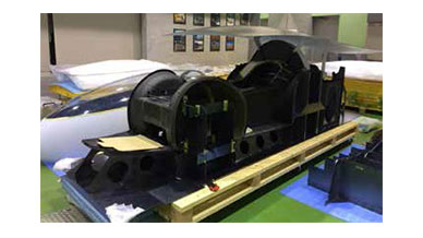
and rigidity against collision from all directions demonstrating that the car was safe for the driver. Fig. 10 shows the final completed monocoque frame.
CFRP body manufacturing
The series of manufacturing processes of the CFRP body, lamination, autoclave, assembly, bonding, and sanding finish, were all conducted by junior students in the second year or below at the cooperative company’s site during the three-month spring
vacation. The design, processes and human resource management was carried out by the senior students resulting in significant growth in teamwork. In particular, as with the instructions from the senior students to the junior students, the analysis
results of Altair HyperWorks were shared, which were immensely useful for the junior students.
Thinning and lighter weight through topology optimization
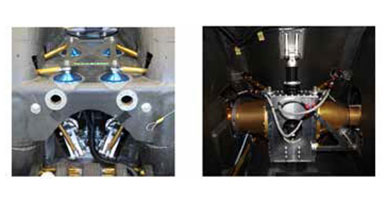
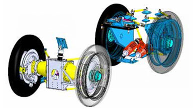
As shown in Fig. 11 to 14, the front suspension comprises of the positive caster trail layout, multi-link, and pull-rod type suspension. The rear suspension comprises of the rigid type, multi-link, and four-wheel steering. This unique suspension structure
was decided upon, based on the integrated design of the suspension in consideration to the shape of the vehicle and its running performance.
Among the components, the large metallic part was provided with the necessary rigidity by using topology optimization based on Altair Inspire™, achieving a weight reduction (see Figs. 15 and 16). In addition to the three external forces of “push-up
force,” “braking force,” and “lateral force,” the moment based on the offset between the tire load part and the spindle installation part was considered as a load condition.
The rib arrangement and locations to be thinned were taken into consideration by the designers with reference to the results of topology optimization. Optimization was repeatedly carried out by re-checking the stress (Fig. 17) and displacement. Since
several components are assembled together to form a unit, the design of the unit was a priority.
For example, since the upright is clinched by the spindle, the displacement of both was added up, and a displacement that does not affect the suspension geometry was given priority. In this way, by referencing topology optimization, the unit design and
the intent of the designers was given priority.
Finally, a model that takes processability into consideration was created. For example, the box-type part in the center of the rear beam structure shown in Fig. 19 was not formed as a single part that involves cost and processing time. Instead, it had
six sheet-like components assembled together with fixed pressure by tightening several M4 screws in order to reduce the cost and the processing time.
Advantages of Using Altair HyperWorks
The Kogakuin University solar team widely used Altair HyperWorks in the car design in the following ways.
- CFRP body structure and lamination plan
- Frequency analysis of extremely thin wing (clarification of fluttering)
- Proof of safety
- Lighter weight of metallic parts through topology optimization
- Optimization of CFRP and metal joining area
In consideration of the type of carbon fibers, orientation, number of ply, honeycomb thickness, etc., maximum reduction in weight was realized through the optimization of the rigidity after confirming surplus strength. By performing rigidity analysis
using Altair HyperWorks for a model imported from 3DCAD, lamination planning could be carried out effectively. This was also useful in sharing technical information through academic and industrial linkage with companies. By performing quantitative
information sharing for processes to be optimized, lamination planning could also be reflected in the design from a technical viewpoint.
Future Objectives
Designing has already begun for the BWSC to be held in 2019. It is anticipated that motion analysis using Altair MotionSolve™ and Altair MotionView™ will be incorporated into the process for future vehicle design.
Listed below are HyperWorks® applications. Copyright© 2018 Altair Engineering Inc. All Rights Reserved for: HyperMesh®, HyperCrash®, OptiStruct®, RADIOSS®, HyperView®, HyperView Player®, HyperStudy®, HyperGraph®, MotionView®, MotionSolve®, HyperForm®, HyperXtrude®, Process Manager™, Templex™, Data Manager™, MediaView™, BatchMesher™, TextView™, HyperMath®, Manufacturing Solutions™, HyperWeld®, HyperMold®, solidThinking®, solidThinking Evolve™, solidThinking Inspire®, Durability Director™, Suspension Director™, AcuSolve®, AcuConsole®, HyperWorks On-Demand™, HyperWorks Enterprise™, PBS Works™, BS Professional®, GridWorks™, PBS GridWorks®, PBS™, Portable Batch System®, PBS Analytics™, PBS Desktop™, e-BioChem™, e-Compute™ and e-Render™. All other marks are the property of their respective owners.


