Altair Inspire Finite Element Analysis of a Christmas Tree Stand
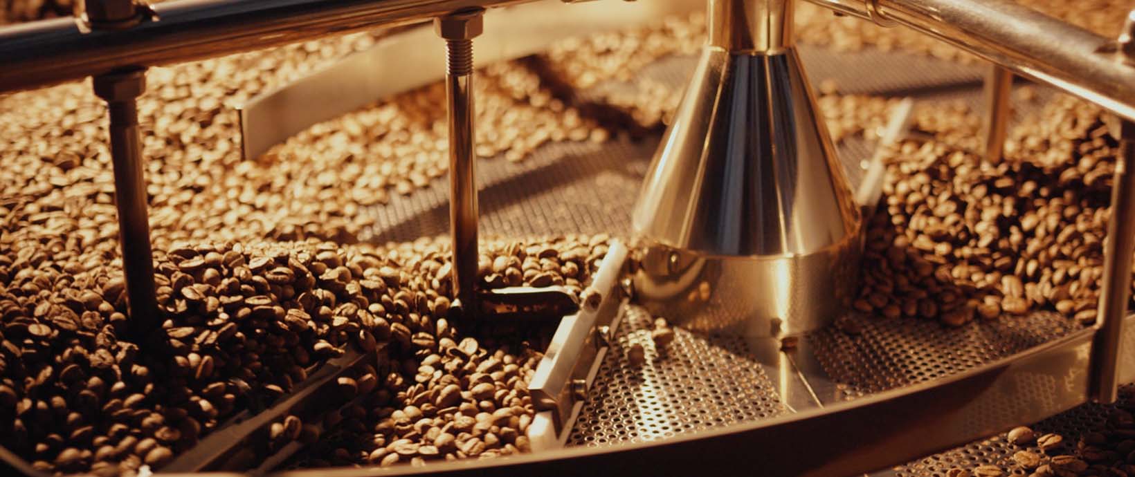
Every year on the Friday following Thanksgiving, The Brennan family ventures out to a tree farm and gets the biggest pine tree we can find to fill our family living room. Our trees usually range from 14-17 feet tall and can weigh up to 350 lbs. Keeping these large trees safely upright has always been a struggle; usually involving safety ropes tied to the handrails because the stand at the bottom isn’t strong enough to support the unstable tree. This year however, we found a tree stand that seemed to be up to the task! This tree stand is made of over 70 lbs of welded steel and uses four large threaded rods to hold the tree locked in place. I used Altair Inspire to model and analyze the current design as an exercise in proper simulation practices in Inspire as well as a benchmark strength test for the tree stand.
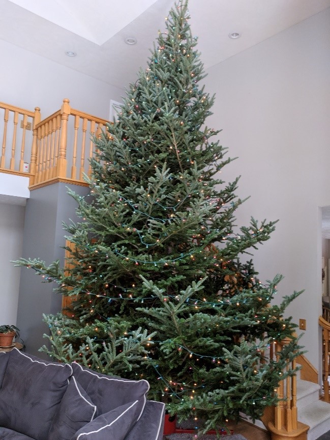 Brennan Family Christmas Tree 2018.
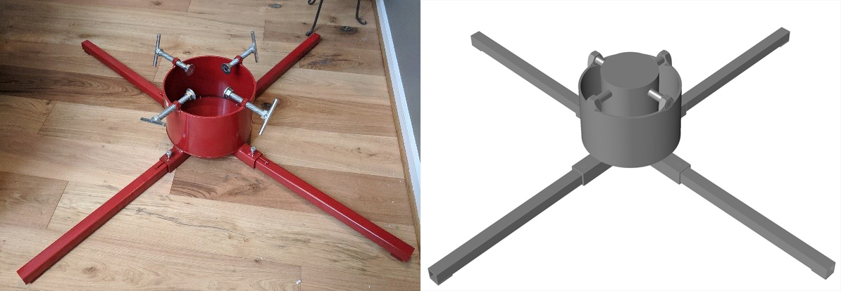 Stand real photo versus Altair Inspire CAD geometry.
Altair Inspire provides a great platform for quickly and accurately running many different finite element (FE) models with an extremely friendly and easy to learn user interface. The ability to define complex loads, constraints, and contacts with the click of a button makes testing and iterating through different load cases fun and easy. Quickly visualizing and analyzing the results of a FE model and tuning the geometry or loading in the same window simplifies the sometimes-tedious process of traditional FEA.
Loading
Loading this tree stand realistically means simulating the loads that a real +14 ft tree would impart on the stand. This includes the weight of the tree straight down on the base and, more significantly, the moment created by the tree’s natural tendency to tip over. This load is transmitted through the base and the four screws that, when tightened, keep to tree stable.
Concentrated masses are often used in FEA to model large/heavy objects that don’t need to be modeled exactly but have an impact of the behavior of the rest of the model. Throughout this demonstration, I will use a concentrated mass (500 lb) placed at the approximate center-of-gravity of the tree and horizontal gravitational loads to simulate the tree’s tendency to tip over.
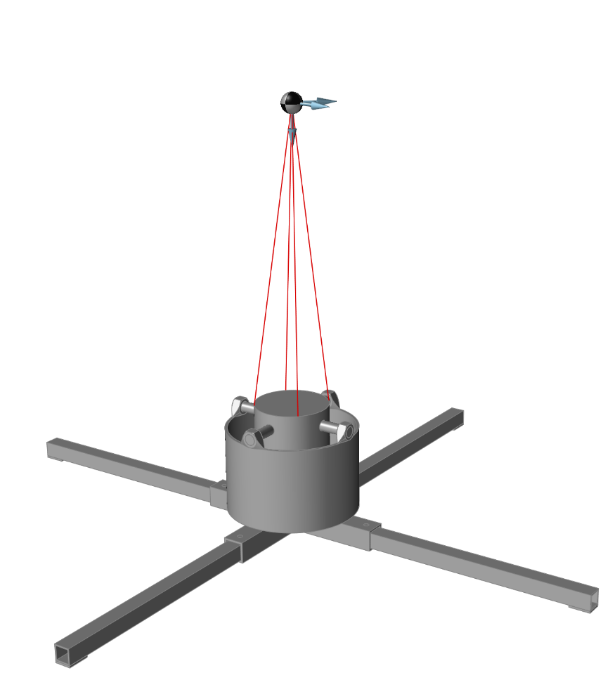 The loading consists of two horizontal loads of 4g (one parallel with a leg and one 45⁰ shifted from that) and one vertically down of 2g.
Constraining
Constraining a finite element model is often the most difficult and subjective part of the process. Different constraints can lead to vastly different results and some are more realistic than others. Supports in Inspire can be fixed or freed in all 6 degrees of freedom which can be used to develop realistic constraints. Constraining involves not only the supports but also the contacts between parts and how they are allowed to move and interact when deflections occur.
Exploring many different constraint combinations and comparing the results to one another is an important part of the FEA process and Inspire makes it easy and fun.
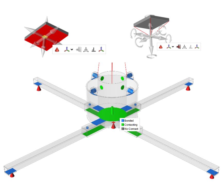 All 6 degrees of freedom for supports and contacts in the tree stand model.
Fixed Supports
The initial reaction of most new Inspire users is to constrain all the faces that contact the ground with supports that are locked in all 6 DOF. This is an easy baseline analysis to run and check to see if the geometry and contacts are modeled correctly however this is clearly not a realistic support case and we’ll see why.
Surfaces that are welded together are designated as bonded (blue) while others are defined as just contacting (green) meaning they’re allowed to separate from each other but won’t intersect.
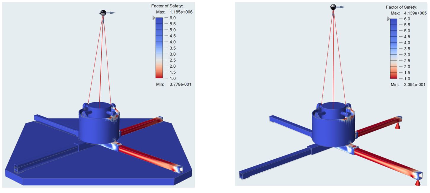
Fixed Supports Results
Parallel Load Case
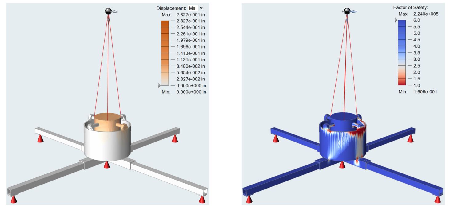
45⁰ Load Case
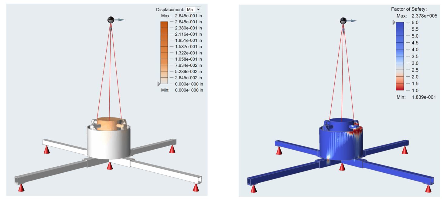
The high stress areas are in the welded nuts and bolts that directly support the tree. While this area is most likely a weak point in the model due to thin welds, the stress should be distributed into the base and legs of the model as well but the fixed support in the middle of the base forces the stress through only the bowl/base and into the ground or support. The legs are left without any of the load because the model is over constrained and not acting realistically. I will explore a few more load cases and model iterations to approach more realistic loads and constraints.
Sheet Support Model
In attempt to get one next step closer to reality, I will model in a large sheet representing the floor of the room the stand/tree would sit upon. Modelling the rigid floor and using different kinds of contacts to explore their effect on the model may prove to be more realistic than the support constraints in previous cases.
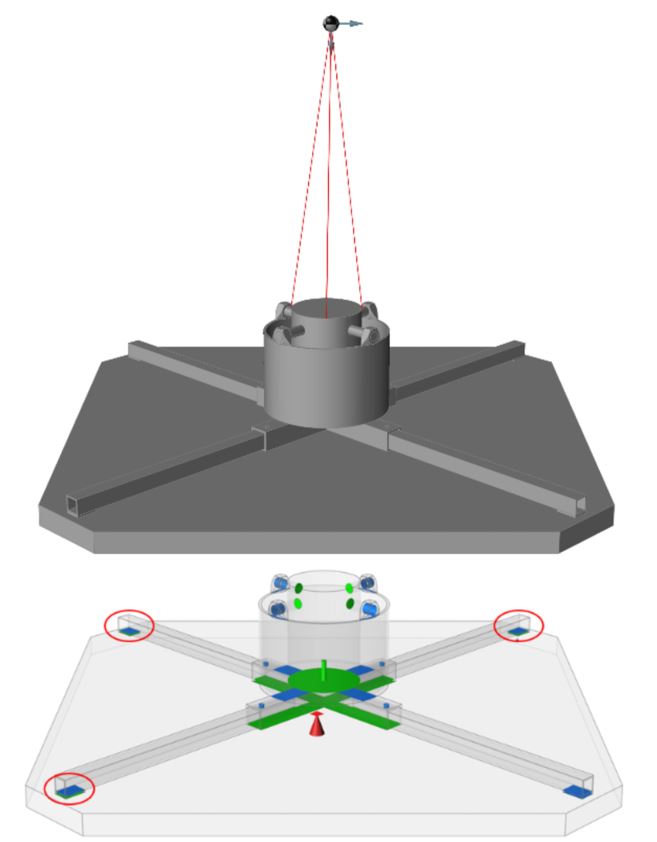
Simultaneously, we will attempt to model the same situation with support constraints and compare the results from both.
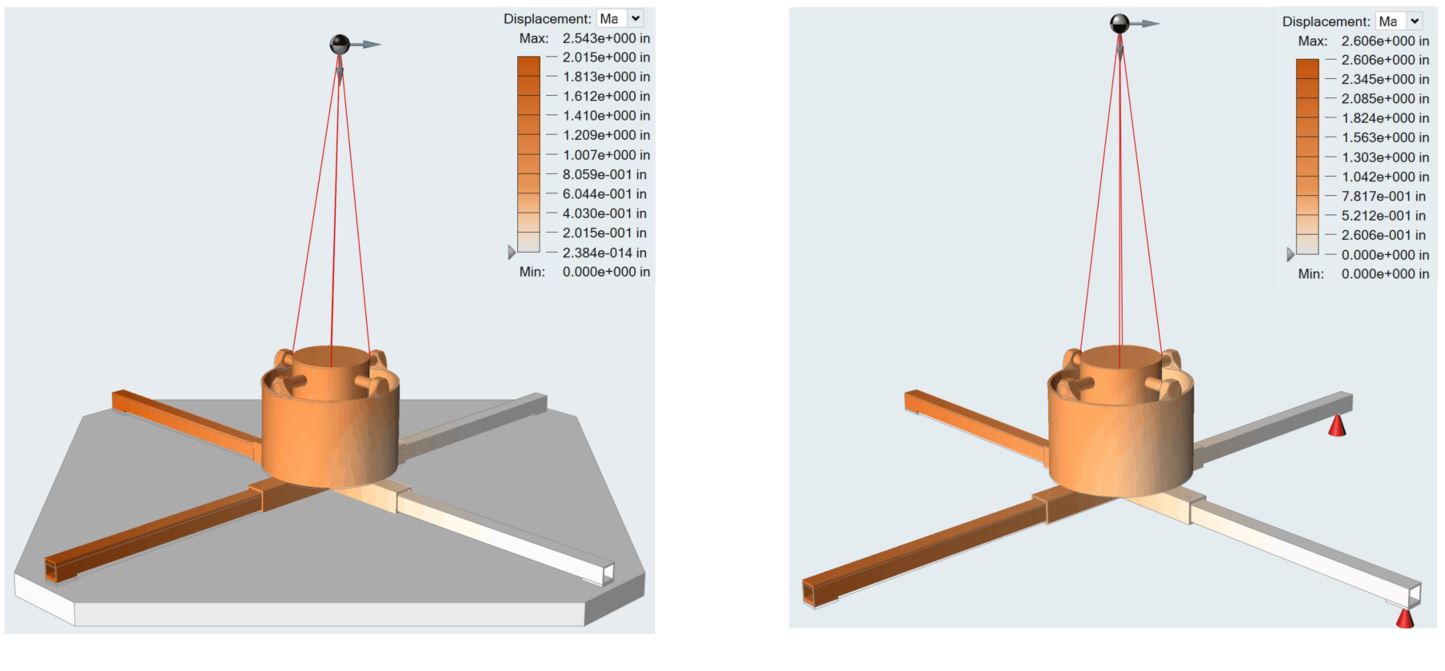
What we are attempting to simulate is the tree tipping towards one side which would lift up one side of the stand drive the other side into the ground. Instead of locking all four feet of the model, I’ll only use the Parallel load case and leave the three legs that are not parallel with the force unconstrained: meaning unbonded contacts in the sheet model (circled in red) and unsupported in the mimic.
I’ll refer to this run as the “Single Locked Foot.”
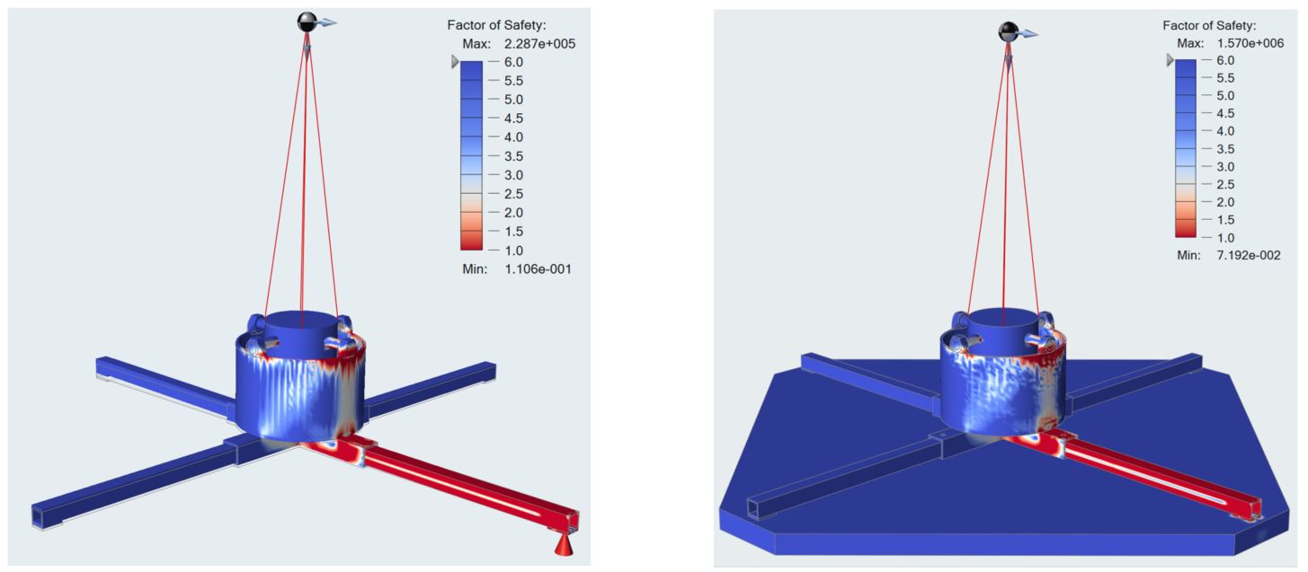
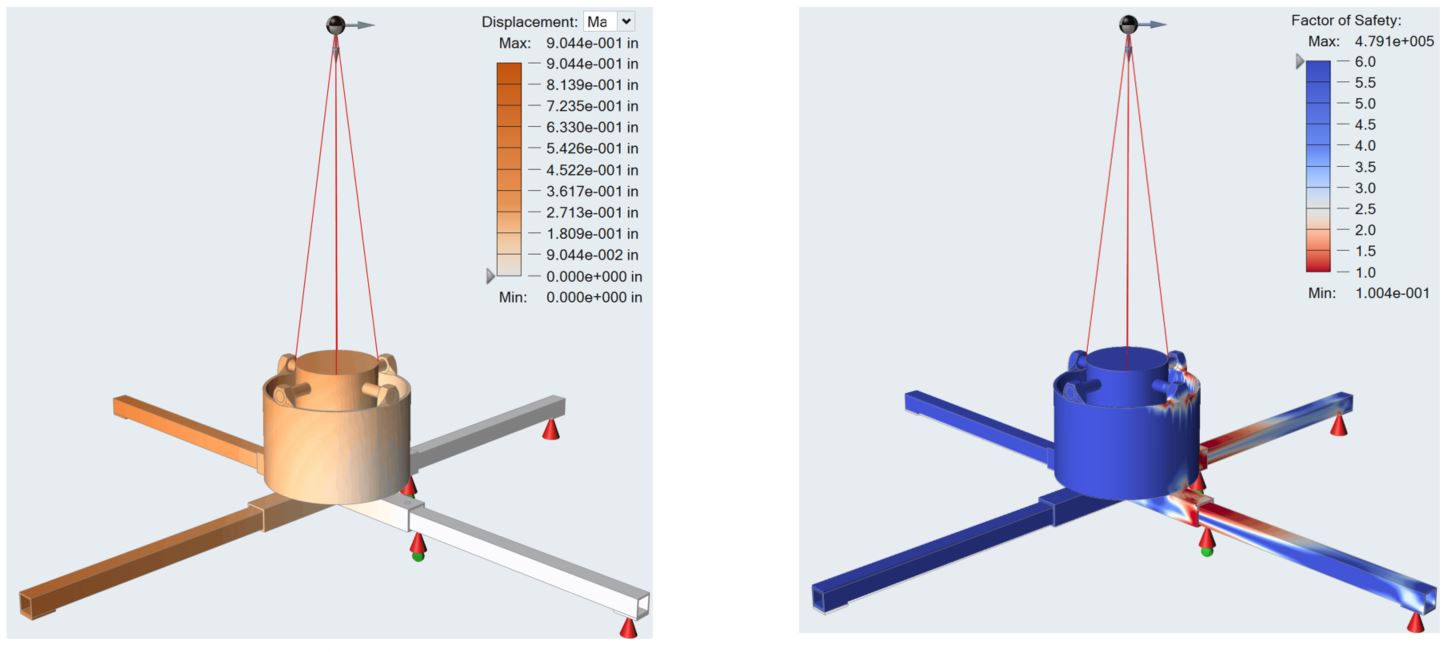
The results from the sheet supported, single locked foot model show very large displacements and stresses in the leg that’s attached to the locked foot. This is what we should expect from such large loads being forced into one support on a small area. Also, we see that the results from the sheet model and the Inspire supported model mimicking it are quite similar. Although these results are expected, they are still unrealistic because the tree and stand would never deform this much without tipping to one side of the single leg subsequently sharing the load with another leg. Therefore, a more realistic model would use the 45⁰ Shifted load case and lock the two feet that point in the direction of that load while unlocking the feet on the other side of the model. I’ll also turn the G-loads down to 2g everywhere so the stresses and displacements aren’t as intense. I’ll refer to this model as Double Locked.
This model is very close to what we would expect to happen if the tree were to start to tip over. The stress moves through the bolts that contact the trunk and into the legs which bend. The only issue remaining is that the base lifts off the ground still due to the load at the top being applied directly to the side and the base being free to lift off. To limit this lifting, I see two possible solutions: Lock the edge that is lifting off vertically (either with support or contact) or direct the load 30⁰ downwards to simulate the tree falling down.
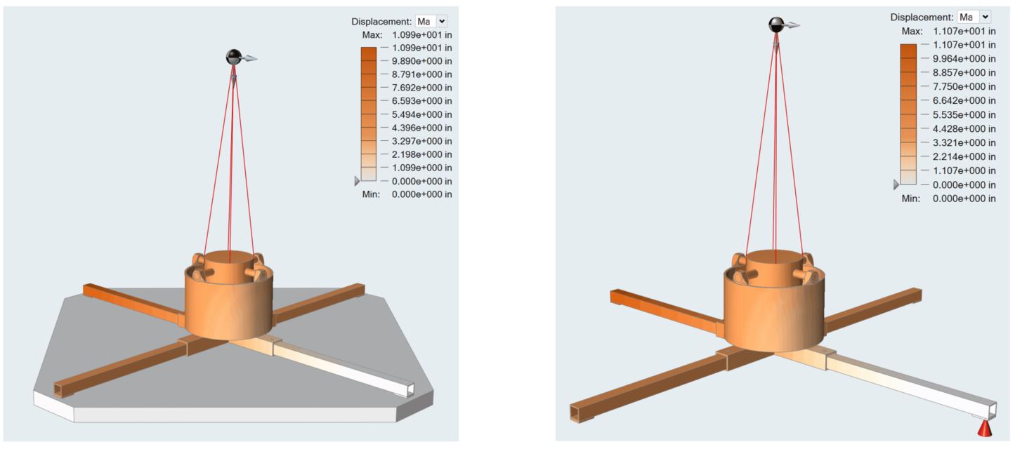
Base Edge Support Model
Downward Angled Load
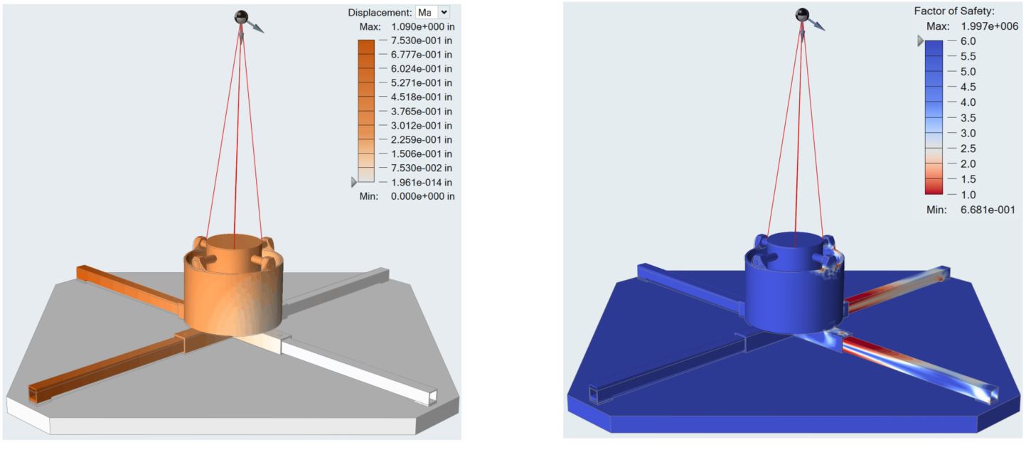
The previous two models are what I would consider realistic deflections and stresses for the scenario that is being simulated. The tree tipping would drive stress through the bolts which are a point of stress concentration due to the thin welds. The two legs in the direction of the tip share the load and bend, causing high stress near the connection point to the base. There is no unstable deflection or lifting off the ground due to our tuned constraints. All of this iterative loading/constraining process was done in just a few days with each run being under 15 minutes. The FEA process using Inspire’s user-friendly interface is fast, easy, and accurate. The ability to quickly define complex loads, constraints, and contacts is unmatched. In future blogs I will explore how to use Inspire’s topology optimization tools to strengthen this design and compare results back to the baseline analyses I did today.