
Efficient Automation, Control, and Optimization of Thermo Fluid Systems using Flow Simulator
By Aditya Jayanthi, Thermal Solutions Product Manager, Altair.
In the Turbomachinery industry, thermo fluid system design is a creative process undertaken to solve new or existing problems that are often complicated because of the complex nature of fluid flow, and of heat and mass transfer mechanisms that govern the system. It is an extremely important task because it leads to new and improved designs. It often involves an open-ended solution with multiple possibilities, and is contrasted against analysis, which gives rise to unique, well-defined, closed-ended results. Thus, thermo fluid system design generally involves considering many different solutions, and finding an acceptable result that satisfies the given problem. Synthesis brings several different analyses and types of information together, thus forming an important facet in system design. Figure 1 below outlines the common practice adopted by Turbomachinery companies for efficient automation, control and optimization of thermo fluid systems applications.
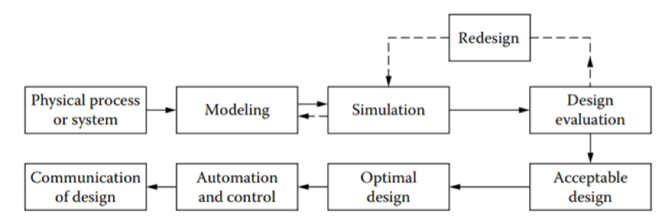
Figure 1: Steps involved in design and optimization of thermo fluid system models
Due to the increasing worldwide competition, and the need to develop new, improved, and more efficient gas turbines, growing emphasis is being placed on Thermo fluid system design. Altair Flow Simulator is available to Altair customers, providing a unique platform for rapid design of thermo fluid system applications of the gas turbine industry. Flow Simulator provides a variety of automation and optimization capabilities as shown in Figure 2 for Thermo fluid system design.
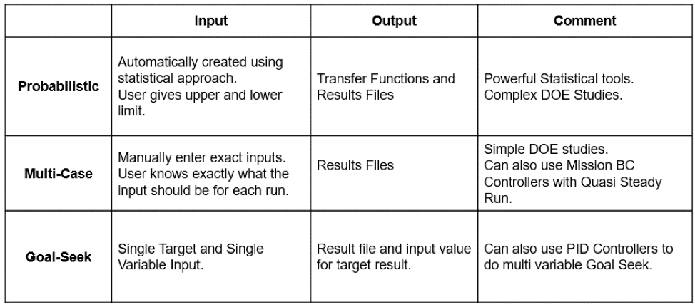
Figure 2: Automation and Optimization methods available in Flow Simulator
Additionally, Flow Simulator also provides a variety of controllers as shown in Figure 3 to perform several “what if studies.” Controllers are used to change the chamber and element inputs while the solver is running. They use “gauge” variables to “manipulate” the chamber or element inputs. For example, you can change a valve position (manipulate variable) based on chamber pressure (gauge variable)
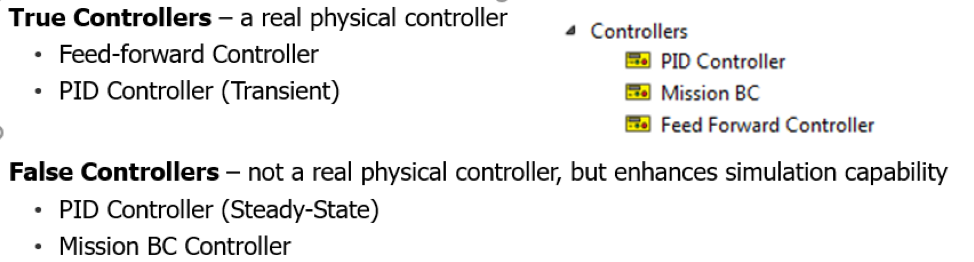
Figure 3: Controllers available in Flow Simulator
Modifications in the Design of Existing Systems
In many cases of turbomachinery applications, existing or available components may form the basis for the design of a new system to meet the given requirements and constraints. This is clearly the simplest approach for obtaining a conceptual design for the given problem. The main idea here is to employ existing systems as the basic framework for design and to consider variations in different components or parts of the system to satisfy the new design conditions. The overall configuration of the system is kept largely unchanged and only a few relevant components or subsystems are varied.
In the example shown in Figure 4, a Proportional Integral Derivative (PID) controller is used in goal-seek analysis to adjust the area of orifice (element 4) until the target flow rate is achieved. The gauge variable is set to the flowrate of element 3, (pipe) and the manipulated variable is set to an area of element 4 (area). The minimum and maximum variable values of the manipulated variable are provided along with necessary tuning parameters for the PID controller. In this example, most of the system is kept unchanged except the orifice element.
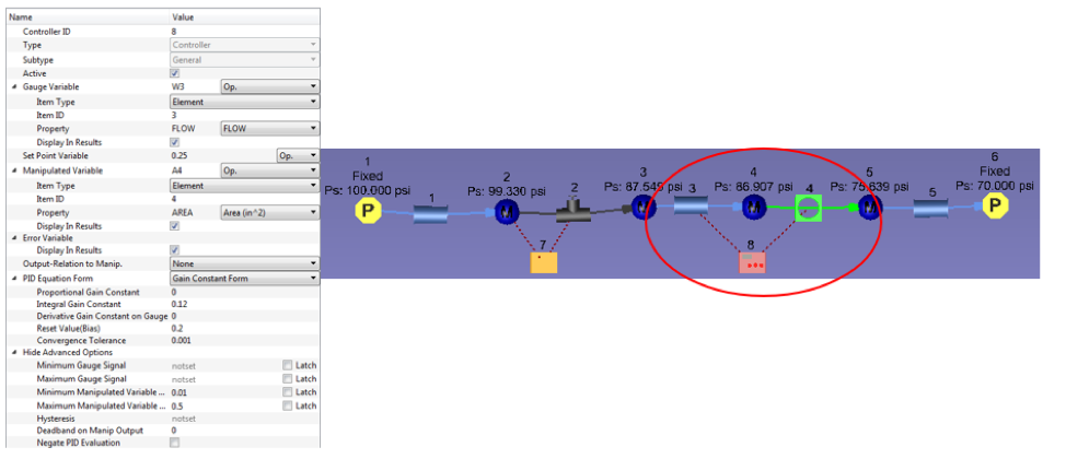
Figure 4: Example model showing PID controller used in goal-seek analysis
Another example shown in Figure 5 is also a common application in gas turbine fluid systems. Here, a feed forward controller is regulating the position of pressure relief value based on upstream pressure. This example shows the powerful options available in Flow Simulator to define any complex control logic using python scripting.
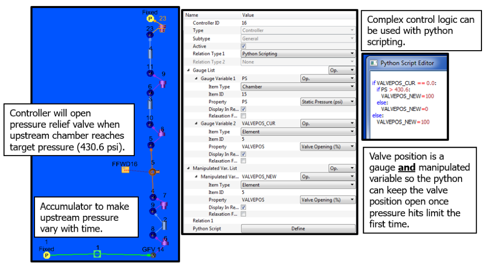
Figure 5: Feed forward controller used in designing of thermo fluid system model
Probabilistic Analysis of Thermo Fluid System Design
Probabilistic analysis is one of the most important elements in the design and optimization of thermo fluid systems. Generally, experimentation on a prototype of the actual thermo fluid systems is very expensive and time consuming. One must depend on simulation based on a model of the given system to obtain the desired information on the system behavior under different conditions. A one-to-one correspondence is established between the model and the physical system by validation of the model. Then the results obtained from a simulation of the model are indicative of the behavior of the actual system. Simulation can be used to 1. Evaluate different designs for selection of an acceptable design 2. Study system behavior under off-design conditions 3. Determine safety limits for the system 4. Determine effects of different design variables for optimization 5. Improve or modify existing systems 6. Investigate sensitivity of the design to different variables
In the simple example shown in Figure 6, our aim is to study the effect of flow rates variation on the pressure drop across the orifice. All the detailed steps involved in design of experiments (DOE) generation are illustrated in the figure. Once the DOE’s are created and Flow Simulator completes the runs, the user can create transfer functions and analyze them. Figure 7 shows the comparison of the results between the actual model predictions and the results of the transfer functions, which for this simple model are almost identical.
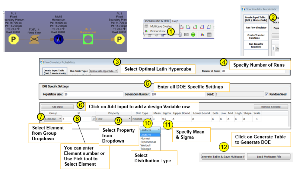 Figure 6: A simple model demonstrating set up of DOE in Flow Simulator
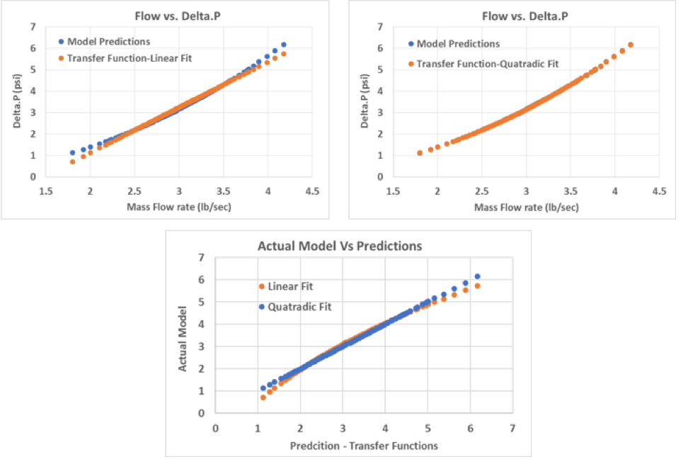
Figure 7: Comparison of results of actual model and transfer functions
Predicting the behavior of the thermo fluid system under off-design conditions, i.e., values beyond those used for the design, is highly essential in gas turbine design. Such a study provides valuable information on the operation of the engine and how it would perform if the conditions under which it operates were to be altered, as under overload or fractional-load circumstances. Gas turbines seldom operate at the design conditions, and it is important to determine the range of operating conditions over which they would deliver acceptable results. The deviation from design conditions may occur due to many reasons such as variations in energy input, changes in the characteristics of the components with time, changes in environmental conditions, and shifts in energy load on the system. The results obtained from simulation under off-design conditions would indicate the versatility and robustness of the system. It is obviously desirable to have a wide range of off-design conditions for which the engine performance is satisfactory. Flow Simulator’s mission analysis would allow gas turbine engineers to study all possible off-design conditions and estimate the thermal reliability of the design. An example of mission analysis panel is shown in Figure 8.
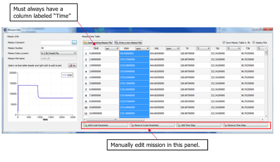
Figure 8: Example mission file in flow simulator
Interested in learning more? Explore the features and capabilities of Flow Simulator