
System of Systems Simulation Accelerating Mechatronic Product Development
Pressures surrounding increases in product complexity, efficiency, performance, cost, and shorter time-to-market lead industries to reevaluate and improve the development process. Various strategies can address each of these challenges independently but not many can provide a clear road to solve all of them.
System integration – both at the forefront of development and in later development stages – can help to improve the quality of the development process, reduce technical risks, and achieve the aforementioned goals while incentivizing collaboration between historically independent engineering groups. For instance, some subsystems can be better designed with information derived from the simulation of others; or their effect on the whole system can be investigated with models of different fidelities.
To explore the benefits of a holistic system development approach, it is worth revisiting this upright scooter example as it combines lightweight mechanical structures, motion dynamics, e-motor drives, and corresponding controls.
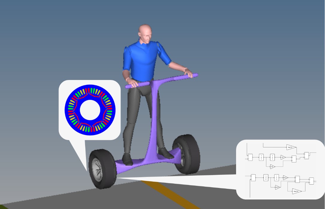 The multibody model has the motor torque as inputs. Motor torque is calculated by the electromagnetic motor models with currents driven by the controllers.
Making design decisions early
Designing the mechanical subsystem of the upright scooter is an independent process. Lightweighting is one of the most important factors to improve efficiency and performance. With the mechanical subsystem modeled, investigating the motion dynamics can take place, but the resulting model can also help in designing both the controller and the motor subsystem.
The design of the controls and the motors can follow the same approach and be independent processes. In fact, this has historically been the solution. During the development of the controller the mechanical model is reduced to a simple mathematical model and is only used in validation. The result is a tuned proportional–integral–derivative (PID) controller. PID controllers are still the most widely used control scheme but there is no “one size fits all” when it comes to controllers. For multi-variable control problems PIDs are insufficient. Also, parameter tuning is a time consuming process that often relies on trial and error.
Controlling a self-balancing upright scooter is a multi-variable process. Controls are needed for both the transverse and the longitudinal planes. Instead of a PID, different control schemes (like an optimal controller) need to be used. To be designed, optimal controllers need an accurate reduced order model (ROM) of the mechanical subsystem in the form of state space matrices (ABCD matrices). The solution to that was to use Altair MotionSolve™ to linearize the model and then extract the required ABCD matrices. Through these ROMs two respective optimal controllers were built in Altair Activate® for each plane.
Likewise, the design of the motors has typically been an independent task of a siloed group. There is some data exchange (like size or torque profiles) during the early development stages to provide the requirements for the motors. The stability, performance, and even efficiency of the system are all impacted by the quality and accuracy of these requirements. Still, the calculation of accurate requirements does not warrant against a siloed motor design group, but it highly motivates the most accurate simulation of the other two subsystems. To create a more accurate torque profile, high fidelity models of the controller and mechanical subsystems can be used in co-simulation. Activate provides accurate controls as the built-in MotionSolve block functions as an integration platform allowing the co-simulation with the multibody MotionSolve model. This provides a highly accurate torque profile, leading to improved system performance, stability, and efficiency. With a clear set of requirements, we moved on to design the motors with Altair Flux™.
Holistic design exploration
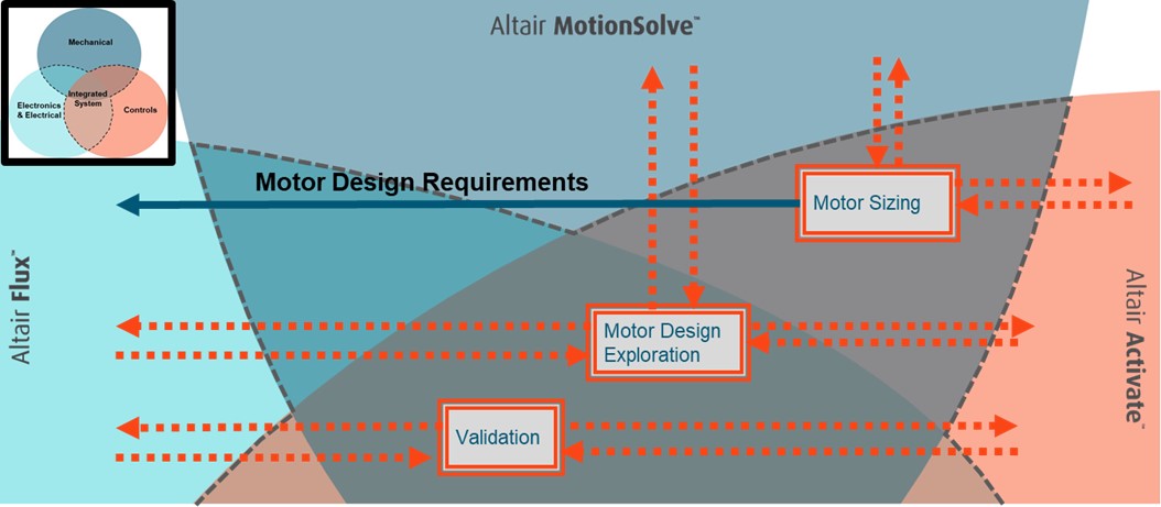 Integrating the mechanical, electrical (motors), and controls subsystems are necessary to provide design requirements for the motor, to explore the motor’s design, and to validate the performance of the system.

[embed]https://altair-2.wistia.com/medias/g3gtwdgtgf#[/embed]
While each independent subsystem goes through a circle of design and optimization, there are further opportunities to improve a product when the system is viewed as a whole. For instance, even though the motors were optimized independently, we could select different designs to investigate their effect on the whole system. Each motor was tested in different driving and road profiles: a) start and stop with maximum velocity on smooth road; b) lane change/turning on smooth road; c) uphill climb on smooth road; and d) rough road.
For multiple, rapid simulations, critical during design exploration, it is recommended to create a ROM for each motor design. To do this, Flux was used to create a magnetostatic look-up table which describes the behavior of the motor. This provided the best of both worlds; a significantly more accurate motor model and a typical simplified, analytical model which still allowed for rapid simulation.
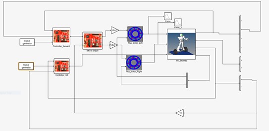 This is a system-of-systems model showing longitudinal and transverse plane controllers in co-simulation with FEA motor models and a multibody model.
System validation
Even though the system performance was investigated during design exploration, it is best to look at the final system in more detail. The use of a motor ROM provides a good first indication, but it is important to take higher harmonics into account and then replace it with the high-fidelity model in co-simulation with the models of the mechanical and controller subsystem. During validation all subsystems were in co-simulation with Activate utilizing both of the built-in MotionSolve and Flux blocks, simulating the system of systems. Through the validation process the system was found to be unstable due to torque ripples, not evident during the design exploration stage. This led to a slight redesign of the control system.
Without in-depth simulation of the whole system the instability would have been found at a later stage, significantly increasing development time and possibly costs.
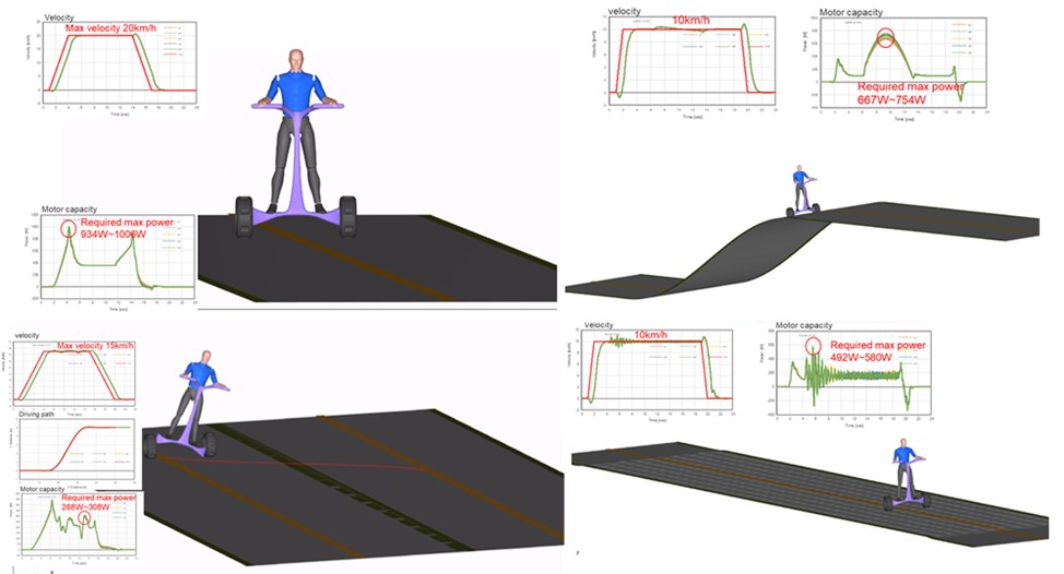 Validating the system with four tests: 1. Start and stop with maximum velocity on smooth road; 2. Uphill climb on smooth road; 3. Lane change/turning on smooth road; 4. Rough road
System integration and strategic fidelity switching
To address the pain points and goals mentioned at the beginning of this article it is clear that a more integrated development process is necessary early on in the design cycle. A holistic system development approach with connected subsystems can lead to a more optimized product while reducing the time-to-market. The choice between complex finite element analysis (FEA) simulation or ROM of each subsystem and the option for co-simulation allows for rapid simulations during design exploration and the in-depth analysis of the finalized design. The easy switch between high fidelity models and ROMs reduces development time and promotes a more streamlined, collaborative product development process.
Interested in seeing Altair’s integrated system simulation in action?

System integration – both at the forefront of development and in later development stages – can help to improve the quality of the development process, reduce technical risks, and achieve the aforementioned goals while incentivizing collaboration between historically independent engineering groups. For instance, some subsystems can be better designed with information derived from the simulation of others; or their effect on the whole system can be investigated with models of different fidelities.
To explore the benefits of a holistic system development approach, it is worth revisiting this upright scooter example as it combines lightweight mechanical structures, motion dynamics, e-motor drives, and corresponding controls.
The multibody model has the motor torque as inputs. Motor torque is calculated by the electromagnetic motor models with currents driven by the controllers.Making design decisions early
Designing the mechanical subsystem of the upright scooter is an independent process. Lightweighting is one of the most important factors to improve efficiency and performance. With the mechanical subsystem modeled, investigating the motion dynamics can take place, but the resulting model can also help in designing both the controller and the motor subsystem.
The design of the controls and the motors can follow the same approach and be independent processes. In fact, this has historically been the solution. During the development of the controller the mechanical model is reduced to a simple mathematical model and is only used in validation. The result is a tuned proportional–integral–derivative (PID) controller. PID controllers are still the most widely used control scheme but there is no “one size fits all” when it comes to controllers. For multi-variable control problems PIDs are insufficient. Also, parameter tuning is a time consuming process that often relies on trial and error.
Controlling a self-balancing upright scooter is a multi-variable process. Controls are needed for both the transverse and the longitudinal planes. Instead of a PID, different control schemes (like an optimal controller) need to be used. To be designed, optimal controllers need an accurate reduced order model (ROM) of the mechanical subsystem in the form of state space matrices (ABCD matrices). The solution to that was to use Altair MotionSolve™ to linearize the model and then extract the required ABCD matrices. Through these ROMs two respective optimal controllers were built in Altair Activate® for each plane.
Likewise, the design of the motors has typically been an independent task of a siloed group. There is some data exchange (like size or torque profiles) during the early development stages to provide the requirements for the motors. The stability, performance, and even efficiency of the system are all impacted by the quality and accuracy of these requirements. Still, the calculation of accurate requirements does not warrant against a siloed motor design group, but it highly motivates the most accurate simulation of the other two subsystems. To create a more accurate torque profile, high fidelity models of the controller and mechanical subsystems can be used in co-simulation. Activate provides accurate controls as the built-in MotionSolve block functions as an integration platform allowing the co-simulation with the multibody MotionSolve model. This provides a highly accurate torque profile, leading to improved system performance, stability, and efficiency. With a clear set of requirements, we moved on to design the motors with Altair Flux™.
Holistic design exploration
Integrating the mechanical, electrical (motors), and controls subsystems are necessary to provide design requirements for the motor, to explore the motor’s design, and to validate the performance of the system.Interested in seeing Altair’s mechatronics simulation in action?
[embed]https://altair-2.wistia.com/medias/g3gtwdgtgf#[/embed]
While each independent subsystem goes through a circle of design and optimization, there are further opportunities to improve a product when the system is viewed as a whole. For instance, even though the motors were optimized independently, we could select different designs to investigate their effect on the whole system. Each motor was tested in different driving and road profiles: a) start and stop with maximum velocity on smooth road; b) lane change/turning on smooth road; c) uphill climb on smooth road; and d) rough road.
For multiple, rapid simulations, critical during design exploration, it is recommended to create a ROM for each motor design. To do this, Flux was used to create a magnetostatic look-up table which describes the behavior of the motor. This provided the best of both worlds; a significantly more accurate motor model and a typical simplified, analytical model which still allowed for rapid simulation.
This is a system-of-systems model showing longitudinal and transverse plane controllers in co-simulation with FEA motor models and a multibody model.System validation
Even though the system performance was investigated during design exploration, it is best to look at the final system in more detail. The use of a motor ROM provides a good first indication, but it is important to take higher harmonics into account and then replace it with the high-fidelity model in co-simulation with the models of the mechanical and controller subsystem. During validation all subsystems were in co-simulation with Activate utilizing both of the built-in MotionSolve and Flux blocks, simulating the system of systems. Through the validation process the system was found to be unstable due to torque ripples, not evident during the design exploration stage. This led to a slight redesign of the control system.
Without in-depth simulation of the whole system the instability would have been found at a later stage, significantly increasing development time and possibly costs.
Validating the system with four tests: 1. Start and stop with maximum velocity on smooth road; 2. Uphill climb on smooth road; 3. Lane change/turning on smooth road; 4. Rough roadSystem integration and strategic fidelity switching
To address the pain points and goals mentioned at the beginning of this article it is clear that a more integrated development process is necessary early on in the design cycle. A holistic system development approach with connected subsystems can lead to a more optimized product while reducing the time-to-market. The choice between complex finite element analysis (FEA) simulation or ROM of each subsystem and the option for co-simulation allows for rapid simulations during design exploration and the in-depth analysis of the finalized design. The easy switch between high fidelity models and ROMs reduces development time and promotes a more streamlined, collaborative product development process.
Interested in seeing Altair’s integrated system simulation in action?