New Altair SimSolid inertial loads
Translational inertia load
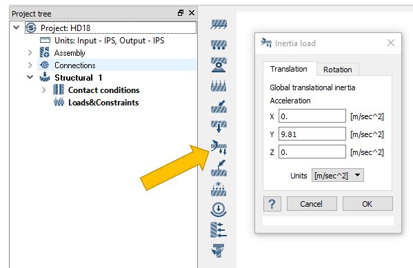
Translational inertia loads are defined in the global XYZ reference frame. These loads are specified in terms of acceleration in a given direction. Note that these loads will be superposed with the gravity load (if present).To define a translational inertia load simply open the load dialog and specify an acceleration and direction value. As a reference, common acceleration values for gravity at sea level are 9.81 m/s^2 or 386.09 in/s^2. Here we define a 1 g inertia load in the global Y direction.

NOTE - Inertia loads act in the opposite to direction specified. An acceleration in the +X direction will cause a force in the -X direction. This is different to the gravity load which has a force in the direction specified.
Rotational inertia load
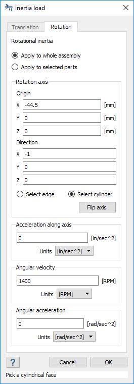
Rotational inertia loads can be applied to the whole assembly or to a selected set of parts. The axis of rotation is defined by a point and direction vector. Select an straight edge or curved cylinder edge to locate the axis of rotation. If necessary, use the Flip axis button to change the way the axis points. Drag the ball to approximately position the origin point, then fine tune the text values on the dialog.
A leaf in the project tree will be created for each type of Inertia Load and the axis will remain on the model with labels for the non-zero values. The Altair SimSolid convention is to use ω for rotational velocity, ε for rotational acceleration and α for axial acceleration.
NOTE - multiple rotational inertia loads can be defined. This implies that rotational inertial can be nested. For example gears attached to other rotating gears.


