New material non-linear analysis now available in Altair SimSolid
Linear structural analysis assumes the relationship of stress to strain is both linear and elastic. “Linear” means the stress is directly proportional to the strain and “elastic” means that all deformations will return to their original state once the loads have been removed. But what happens when these assumptions are no longer valid? In order to predict the structural response accurately, a material nonlinear analysis must be performed. Now with release 3, this option is available in Altair SimSolid.

In Altair SimSolid, Henki-Nagai deformational plasticity theory is used when simulating structures loaded beyond yielding. Isotropic hardening is assumed and unloading results in residual stresses and strains. This model is well suited to ductile materials such as mild steels.

Apply the material to your model and then run a standard static analysis. That is all that is required. Alternatively to other applications, Altair SimSolid does not require setting and management of load increment steps. You just need to specify the full load values. Altair SimSolid will use the specified material data and iterate automatically to evaluate stresses that are beyond the yield stress value.


Stress-strain curves can be created in a number of ways. Individual rows of strain and stress point values can be added one at a time. Select the Add row button, then enter the appropriate engineering strain and stress value. At a minimum, 3 points are required.
Here are are two typical stress-strain curves. The first defines an elastic-perfectly plastic material, the second an elastic-plastic material with linear hardening.


Material nonlinear analysis
In material nonlinear analysis, the stress-strain relationship is given by a curve instead of a single value of the elasticity modulus. This defines what happens once the load exceeds the elastic region limit.
In Altair SimSolid, Henki-Nagai deformational plasticity theory is used when simulating structures loaded beyond yielding. Isotropic hardening is assumed and unloading results in residual stresses and strains. This model is well suited to ductile materials such as mild steels.
How to do a material nonlinear analysis in Altair SimSolid
All that is required is a material definition that includes a complete stress-strain curve. Open the material database and look for materials with an associated stress-vs-strain curve.
Apply the material to your model and then run a standard static analysis. That is all that is required. Alternatively to other applications, Altair SimSolid does not require setting and management of load increment steps. You just need to specify the full load values. Altair SimSolid will use the specified material data and iterate automatically to evaluate stresses that are beyond the yield stress value.
Results evaluation
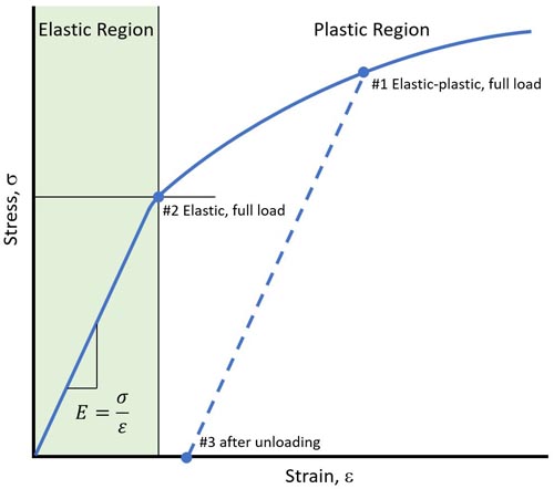
Once the analysis is complete, you can display result plots the usual way, but with one substantial difference: Three result quantities are now available:- Elastic-plastic response under full load – defines the structural response after all nonlinear iterations are complete. See Point #1 on the stress-strain graph below.
- Elastic under full load – defines the response as if the material was linear at the elastic load limit (Point #2).
- After unloading – defines the residual stresses, strains, and deformations once all loads have been removed (Point #3).

Example nonlinear analysis of a 144 part racing car frame
How to create custom material properties
Custom material properties can be created in Altair SimSolid. To do this,select the Material database item from the main Settings menu, and select Edit current. Then right mouse button select a material group and pick Add material. To create a new stress-strain curve, pick the Stress-strain curve button at the bottom of the dialog.
Stress-strain curves can be created in a number of ways. Individual rows of strain and stress point values can be added one at a time. Select the Add row button, then enter the appropriate engineering strain and stress value. At a minimum, 3 points are required.
Here are are two typical stress-strain curves. The first defines an elastic-perfectly plastic material, the second an elastic-plastic material with linear hardening.

Example of elastic – perfectly plastic material definition

Example of elastic-plastic with linear hardening– the tangent modulus (slope of the second line segment) is approximately 10% of the linear elastic modulus
Stress-strain curves can also be read from an external comma separated variable (CSV) files. The format of the file has a header of “strain, stress” and corresponding row of values. Here is an example of one typical file's contents.Strain,stress 0,0 0.005,5.30e8 0.4,5.83e8Finally, curves can be created using a K-n power law function. To do this select the Create by n-value button, then specify K and n. Some sample K-n values for typical materials are given in the pull-down menu.


Example of stress-strain curve created with K-n power law function
Once the stress-strain curve is created, select OK to return the main material dialog. Fill in the other material properties (Poisson’s ratio, density, CTE, etc.) and select the Save material button. Your new material is now ready to use.


