Thought Leader Thursday: From 1D To 3D And Back - Leveraging The Best Of Both Worlds For Model-Based Development
The complexity of today’s products requires the use of simulation models from early concept design to final validation testing. These simulation models need to cover various disciplines, allowing the assessment of the system’s functional behavior and hence optimization with respect to cost, weight, performance, and endurance.
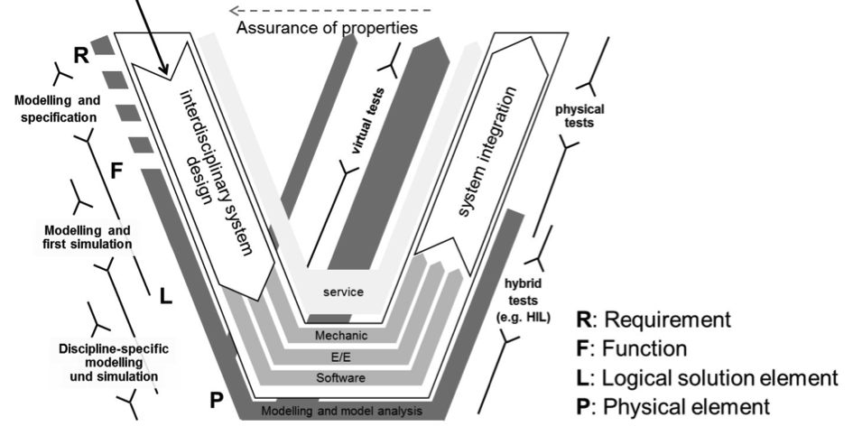
This approach is called MBD, Model-Based Development. As shown below in the extended V-model, models drive the interdisciplinary system design and system integration process.
Given the functional definition of a system, concept design strives to find the optimal physical realization of the various system functions. Simulation models supporting this phase are characterized by:
In the detailed design phase, discipline-specific models are employed for subsystem optimization. They are characterized by:
Due to the different modeling paradigms like abstraction vs. detail and qualitative vs. quantitative, seamlessly transitioning from concept to detailed design isn’t straightforward. It would be desirable to start with the functional structure of the system (functional bill of material) and construct a simulation environment that offers different degrees of model fidelity depending on the available data and the simulation task at hand.
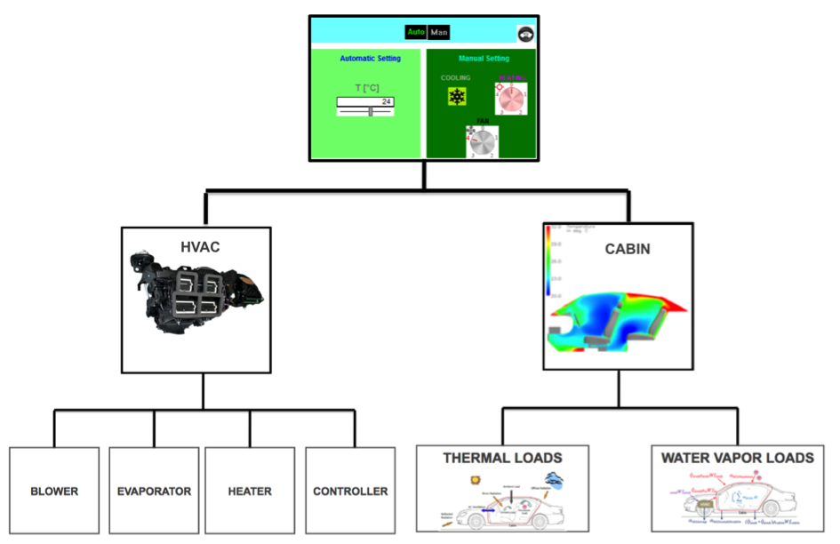
Let’s illustrate an ideal model-based development process by the example of an automotive HVAC system. The simulation model may be constructed as shown in Fig. 2: the man machine interface on the top, the HVAC system (blower, evaporator, heater, and controller) and a model of the cabin (calculating the thermal loads and the water vapor loads) on the lower level.
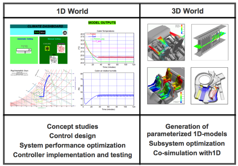
To support the concept design phase, lumped parameter models can be created for the different modules and combined with a simulation environment, as shown on the top left of Fig. 3. The diagrams show a typical simulation of the overall system performance: cooling down to the desired temperature of 24 degrees Celsius and reducing the humidity to a comfortable level.
As explained previously, these models require only a limited set of inputs. The models run fast and allow users to investigate many design variants. We can use them to optimize the overall system, design the control algorithms, and test the controls in a hardware-in-the-loop environment.
The link to the 3D-world can be obtained in various fashions:
CFD models of the various sub-systems combined with Design-of-Experiment techniques can be used upfront to generate parametric 1D-subsystem models or they are employed in the detailed design phase for subsystem optimization. The upper right corner shows various applications.
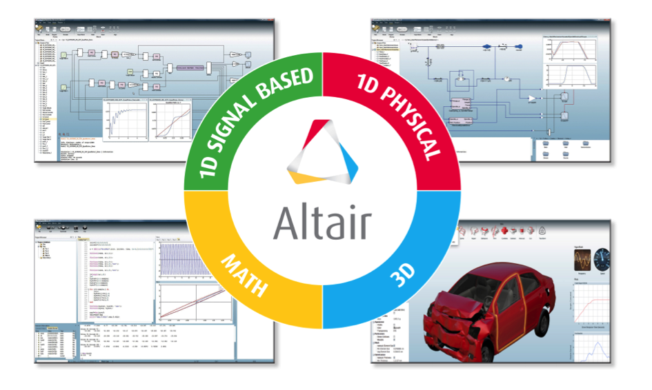
Recently, Altair realized a co-simulation environment, where the 1D-models for the cabin are replaced by a 3D-CFD simulation using AcuSolve. So the question isn’t whether to go for 1D or 3D simulation; we now have the opportunity to combine the best from both worlds while moving more seamlessly from abstraction to detail and from qualitative to quantitative predictions as illustrated below in Figure 4.
If you are interested in combining the best of both worlds for your application, please feel free to share and explore what Altair can do!
This approach is called MBD, Model-Based Development. As shown below in the extended V-model, models drive the interdisciplinary system design and system integration process.
Given the functional definition of a system, concept design strives to find the optimal physical realization of the various system functions. Simulation models supporting this phase are characterized by:
- A huge degree of abstraction (since the available data is limited at this stage)
- The ability to provide directional insight into the system performance
- Short simulation times allowing exploration of lots of design variants
In the detailed design phase, discipline-specific models are employed for subsystem optimization. They are characterized by:
- Little abstraction and huge amount of detailed information (geometry and other data)
- Ability to provide quantitative insight into the discipline specific system performance
- Longer simulation times limiting the exploration of design variants
Due to the different modeling paradigms like abstraction vs. detail and qualitative vs. quantitative, seamlessly transitioning from concept to detailed design isn’t straightforward. It would be desirable to start with the functional structure of the system (functional bill of material) and construct a simulation environment that offers different degrees of model fidelity depending on the available data and the simulation task at hand.
Getting The Best Out Of 1D And 3D Models
Let’s illustrate an ideal model-based development process by the example of an automotive HVAC system. The simulation model may be constructed as shown in Fig. 2: the man machine interface on the top, the HVAC system (blower, evaporator, heater, and controller) and a model of the cabin (calculating the thermal loads and the water vapor loads) on the lower level.
To support the concept design phase, lumped parameter models can be created for the different modules and combined with a simulation environment, as shown on the top left of Fig. 3. The diagrams show a typical simulation of the overall system performance: cooling down to the desired temperature of 24 degrees Celsius and reducing the humidity to a comfortable level.
As explained previously, these models require only a limited set of inputs. The models run fast and allow users to investigate many design variants. We can use them to optimize the overall system, design the control algorithms, and test the controls in a hardware-in-the-loop environment.
The link to the 3D-world can be obtained in various fashions:
CFD models of the various sub-systems combined with Design-of-Experiment techniques can be used upfront to generate parametric 1D-subsystem models or they are employed in the detailed design phase for subsystem optimization. The upper right corner shows various applications.
Recently, Altair realized a co-simulation environment, where the 1D-models for the cabin are replaced by a 3D-CFD simulation using AcuSolve. So the question isn’t whether to go for 1D or 3D simulation; we now have the opportunity to combine the best from both worlds while moving more seamlessly from abstraction to detail and from qualitative to quantitative predictions as illustrated below in Figure 4.
If you are interested in combining the best of both worlds for your application, please feel free to share and explore what Altair can do!


