
Thought Leader Thursday: Worried About Glitches? Try Model-Based Embedded Design
For creating reliable embedded software, look no further than Model-Based Embedded Design (MBED). MBED is an efficient way to use modeling and simulation to speed up the creation of dependable embedded software. You have probably heard about the recent shutdowns of the New York Stock Exchange, United Airlines reservation system, and the Wall Street Journal website due to “computer glitches.” For large organizations, a few minutes of shutdown can greatly impact many aspects of their business operations.
The problem with writing programs in batch languages like C, Java, PHP or Python is that the code is difficult and error prone. Simply one wrong character can cause a major bug and create a glitch in the program. VisSim, a high-level language program acquired by Altair in August 2014, addresses this problem by providing users a simple solution to implement and test algorithms in a visual block diagram form.
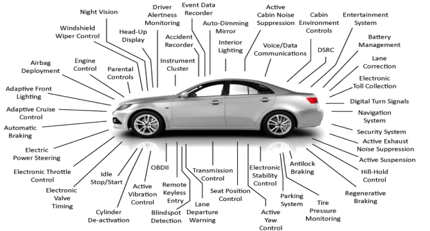 Embedded controllers found in a modern vehicle.

The usefulness of this can be seen in a recent notable problem with the Boeing 787 Dreamliner. Earlier this year, Boeing issued an alert that there was a problem with onboard generator control units (GCUs). As quoted, “after 248 days of continuous power, all four GCUs will go into failsafe mode at the same time, resulting in a loss of all AC electrical power regardless of flight phase.” To recreate this problem, we have to reverse engineer a buggy system that relies on a continuously up counting timer and has no deglitching of a critical error signal. One reasonable use of a timer is to sense rotational speed, and to measure speed, the generators will provide an index pulse to signal a complete revolution. By measuring the time between index pulses and inverting it, we can calculate the speed of the generator. Speed variation from a nominal range is likely the criterion used to shut down a generator. A buggy way to get that time interval is to subtract the time at the current index pulse from the time at the previous index pulse. This works fine so long as your measurement for time resets after each index pulse or has enough precision to handle the lifetime of your device.
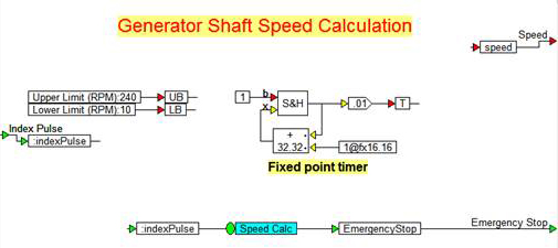
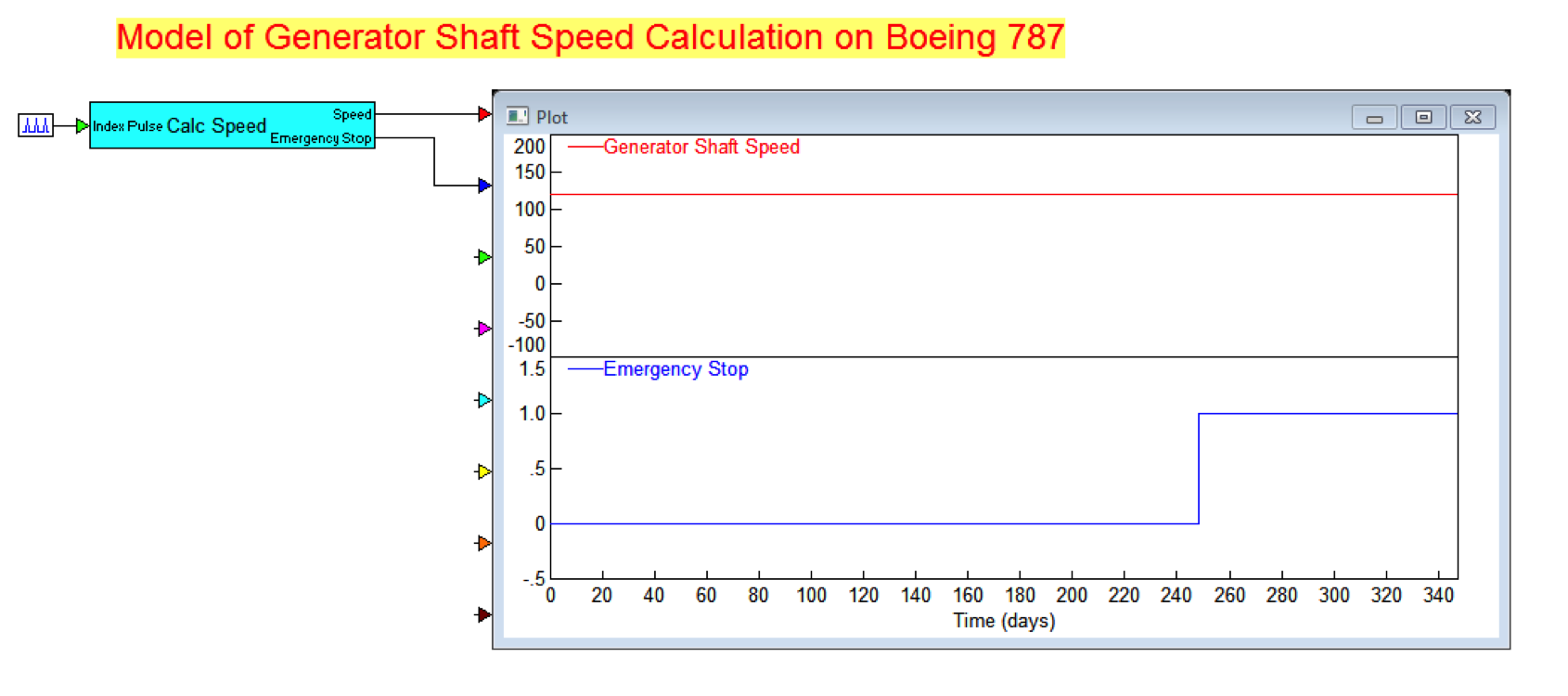
In this case, assuming a signed counter of 32 bits counting at a 100Hz rate, we would expect an overflow at 2.1 billion counts. You could assume that it’s a suitable “infinity” that will outlive our device, but by doing the math, it will actually last for only 21 million seconds. This works out to 357,000 minutes, or 248.55 days. By creating a simple model to measure generator shaft speed from an index pulse, we can run a simulation past the 248 day mark to check. Fortunately, the simulation speed of VisSim allows us to run this model over 5000x faster than real time, which means we don’t have to wait 248 days for the answer! It only takes a little over an hour to hit the glitch. VisSim can simulate a full year of operation of the timer, speed calculator, and shutdown logic in an hour and a half. If the Boeing GCU supplier had used a model-based development tool, they would have seen the problem during subsystem simulation, fixed it in the block diagram and re-simulated to verify correct operation. They then would have been able to generate the embedded code directly from the repaired diagram. Midflight disaster averted.
Model-Based Embedded Development is a powerful tool that can provide the speed of development and reliability required by modern control systems, without spending too much time or money. Contact Altair to learn how VisSim EMBEDDED can save you time, money and embarrassment.
The problem with writing programs in batch languages like C, Java, PHP or Python is that the code is difficult and error prone. Simply one wrong character can cause a major bug and create a glitch in the program. VisSim, a high-level language program acquired by Altair in August 2014, addresses this problem by providing users a simple solution to implement and test algorithms in a visual block diagram form.
Control Engineers Are the First to Adopt MBED
Control engineers have been the major adopters of this method of design, partly due to the difficulty of control design and the high cost of failure in many control applications. With the falling cost of embedded control chips (down to around US$1) and demand for smarter devices, we are starting to see embedded controllers popping up everywhere. For example, automobiles today contain dozens of embedded control loops due to the needs for dependable high-speed communications and control operation. This is happening across various major industries including medical devices, home construction, aviation, process plants, electric generating plants, renewable power, and more. Embedded controllers found in a modern vehicle.Program by Simply Wiring Blocks
In VisSim, the user programs the code by connecting blocks that perform tasks like numerical integration, table lookup, Boolean compare, and other math operations. The user can quickly build models of the controller and the things he wants to control (called the “plant” by control engineers). The controller can be tuned completely in simulation using various optimization techniques. By simulating the controller and plant, problems can be discovered and fixed early in the design process.Generate C Code Automatically
To recognize the controller on an embedded microprocessor, VisSim has a C code generator that is automatically able to translate the block diagram to efficient C code. By supplying blocks specific to the chip, the user can include sensor data like analog to digital converter, or quadrature encoders, actuator signals like PWM, and communication blocks like CAN, SPI or I2C. With JTAG linkage to the target chip, the user can make a change in the block diagram and see it running on the microcontroller in seconds.The VisSim Visual Real-Time Operation System (RTOS)
In most control systems, there is at least one control task, high-level communication task, and debug task during the development. Coordinating these tasks and providing device drivers is the domain of a Real-Time Operation System (RTOS). VisSim provides a visual RTOS whose configuration is integrated into the graphical block diagram. In this way, the application can be completely realized in the diagram with no additional hand coding in C required.The Instructional Case of the Boeing 787
The usefulness of this can be seen in a recent notable problem with the Boeing 787 Dreamliner. Earlier this year, Boeing issued an alert that there was a problem with onboard generator control units (GCUs). As quoted, “after 248 days of continuous power, all four GCUs will go into failsafe mode at the same time, resulting in a loss of all AC electrical power regardless of flight phase.” To recreate this problem, we have to reverse engineer a buggy system that relies on a continuously up counting timer and has no deglitching of a critical error signal. One reasonable use of a timer is to sense rotational speed, and to measure speed, the generators will provide an index pulse to signal a complete revolution. By measuring the time between index pulses and inverting it, we can calculate the speed of the generator. Speed variation from a nominal range is likely the criterion used to shut down a generator. A buggy way to get that time interval is to subtract the time at the current index pulse from the time at the previous index pulse. This works fine so long as your measurement for time resets after each index pulse or has enough precision to handle the lifetime of your device.
In this case, assuming a signed counter of 32 bits counting at a 100Hz rate, we would expect an overflow at 2.1 billion counts. You could assume that it’s a suitable “infinity” that will outlive our device, but by doing the math, it will actually last for only 21 million seconds. This works out to 357,000 minutes, or 248.55 days. By creating a simple model to measure generator shaft speed from an index pulse, we can run a simulation past the 248 day mark to check. Fortunately, the simulation speed of VisSim allows us to run this model over 5000x faster than real time, which means we don’t have to wait 248 days for the answer! It only takes a little over an hour to hit the glitch. VisSim can simulate a full year of operation of the timer, speed calculator, and shutdown logic in an hour and a half. If the Boeing GCU supplier had used a model-based development tool, they would have seen the problem during subsystem simulation, fixed it in the block diagram and re-simulated to verify correct operation. They then would have been able to generate the embedded code directly from the repaired diagram. Midflight disaster averted.
Model-Based Embedded Development is a powerful tool that can provide the speed of development and reliability required by modern control systems, without spending too much time or money. Contact Altair to learn how VisSim EMBEDDED can save you time, money and embarrassment.