Design the Die or the Pattern Right the First Time

NovaStress was launched 2015 as an add-on module to NovaFlow&Solid. At first, many were curious in starting to use this technology since residual stress simulation is harder to grasp compared to casting process simulation, which is just a virtual twin of the casting process so well known by foundrymen in their day to day job. From day one, we have been fighting to make stress simulations more usable and down-to-earth for the foundries. Of course, one aspect is to be able to simulate and get rid of cracks which in certain types of castings is a big problem. The program can also check the dimensional accuracy after a stress simulation has been done.
Die and pattern prediction
We believe that the big use for stress simulations will be what we call die and pattern predictions. Instead of applying a certain percentage value for the liquid and solid contraction onto the die cavity or pattern, you should instead use the simulation program to find what the dimensions of the die cavity or pattern should be.
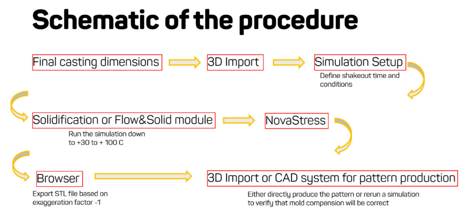
In the NovaFlow&Solid browser, we have a function for exaggerating the displacement. This function is showing the nominal dimensions (before the simulation) when selecting the figure zero (0). After the simulation has been performed with solidification and stresses, you should have the exaggeration factor set to one (1) in order to see how the dimensions and shape have changed from the cavity/pattern to the casting dimensions now after the simulation. The really interesting thing is when you use the exaggeration factor and set it to minus one (-1), because now we take the dimensions from the predicted displacement to a forecast of how the die cavity or pattern should be made.
Now we are making our die/pattern based on the simulation and not a fixed percentage that we know is incorrect already from the start.
The procedure
To make this correct we have found the important points:
- 3D Model should be equal to the dimensions you want in final casting part, not the cavity as in normal simulations.
- Run the simulation of mold compensation with or without feeders and gatings. Do not use the” compensated” feeders/gatings further
- Feeders and ingates can though influence the result but they should not be produced with the compensated shape.
Some examples follow.
- Part 1:
Nominal part + Displaced part
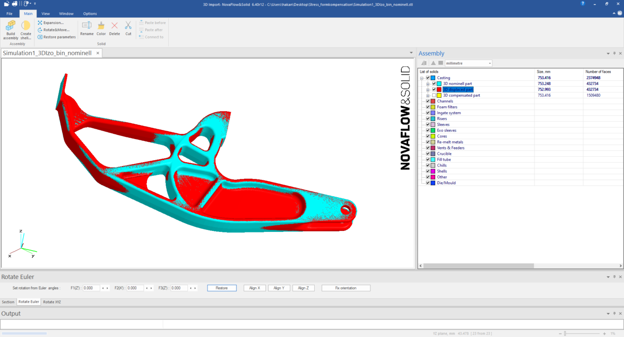
Nominal part + part simulated based on the pattern prediction.
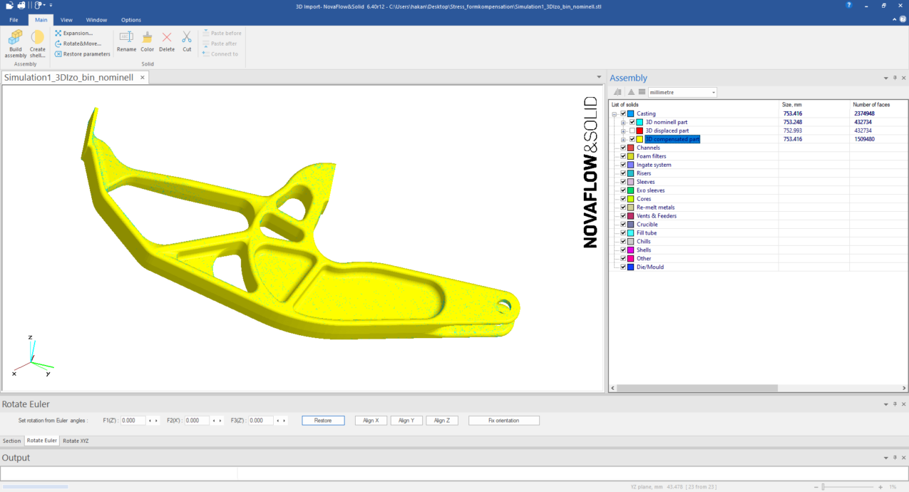
When the blue color from the nominal disappears and you see only the simulated part you have a good match.
- Part 2:
Nominal part + Displaced part
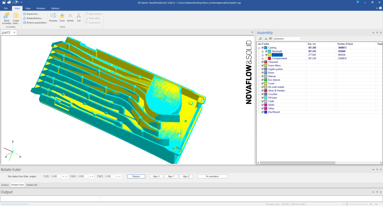
Nominal part + part simulated based on the pattern prediction
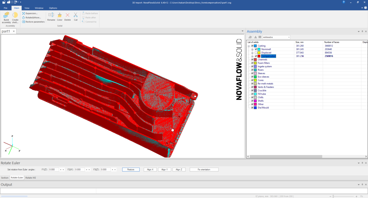
Summary
As you can see, a good match can be achieved and thus the castings are correct in shape and dimensions directly. It is not a matter of changing the design of that casting merely to change the shape of the cavity or pattern to produce correct castings. In some cases, these corrections can lead to undercuts, which will lead to a hard time getting the casting out of the mold or to produce the mold. In such cases, the only chance is to go back to the customer and ask for advice regarding how the product can be changed. You can of course also find ways by adding a core a slider (high pressure die casting) that can assist you in removing the mold or casting. I would say nothing is impossible, just a little bit harder and might take longer time. Some casting parts are prone to distort simply because of the casting design. This is something that needs to be fixed early and the optimal way is that the casting designers already at the design stage takes this into the design loop.


