Game Changer: Including More Physical Effects in CAE Simulation Improves NVH Prediction Capability
This is part three of the four-part series on Automotive NVH comfort based on the paper, “Improving Vehicle NVH CAE Prediction Capability to Prevent Expensive Late Design Changes” written by Andrew Burke, Global NVH Manager at Altair. Click here for parts one and two of the series.
NVH modelling requires an understanding of the level of detail that is necessary to accurately predict dynamic behaviour. An important aspect to this is the inclusion of an appropriate representation of the physics that can influence the response. For example, representation of manufacturing effects is commonly not included in standard NVH solutions. Results of this study show that inclusion of these effects can significantly change NVH predictions, thereby effecting design decisions. Developments in solver and hardware technology have allowed more physical effects to be included in NVH simulations as a standard NVH analysis procedure.
Model Setup
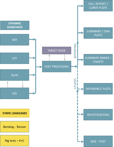
Typical NVH assessment of a trimmed body structure includes suspension and powertrain attachment point static and dynamics stiffness (ESS, DynK), and vibration and noise transfer functions (VTF, NTF), as illustrated in Figure 1.
A study was carried out to demonstrate the effect on CAE trimmed body attachment point stiffness, vibration and acoustic predictions by including physical effects of manufacturing, assembly and trim material behaviour. These effects are typically not included in standard CAE NVH analysis and yet the impact on results is dramatic, leading to very different performance conclusions being drawn and ultimately changes in design direction.
Investigations have been limited to selected components of the vehicle body and selected attachment stiffness and noise transfer function results. Inclusion of all potential body components and CAE analysis at vehicle level would be expected to show further changes in predictions compared to standard simulation methods.
Manufacturing Effects – Panel Forming
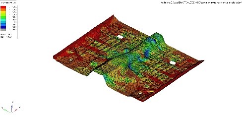
A typical vehicle body structure is largely made of pressed panels spot welded together. The process of panel forming introduces thickness variations that can modify the dynamic performance of a component. This is particularly true for deep drawn pressed panels. Changes in thickness distribution, change the distribution of stiffness and mass, thereby changing component modal behaviour. As an example, Figure 2 shows a thickness distribution contour plot of floor panel.
In the study, thickness distribution due to forming was applied to all major body panels in a batch process, shown in Figure 3. After the forming simulation, the panel thickness distribution is automatically mapped to be used for NVH frequency response analysis. The actual panels considered in this study are shown in Figure 4.
Assembly Effects – Bolt Preload and ContactDuring the vehicle assembly process, components are preloaded by a number of mechanisms. Preloading changes the boundary conditions of components and therefore can affect dynamic behaviour.
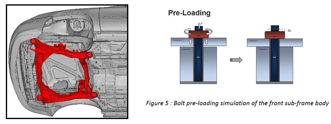
Many vehicle components are assembled using bolted joints. To simulate preloading and contact for all joints during a standard vehicle model build process, would require method and automation tool development. In this study, bolt pretension and contact was limited to the front sub-frame bolted connections to the body, shown in Figure 5. Bolt pretension and contact was applied in an initial loading step prior to frequency response analysis of the preloaded state.
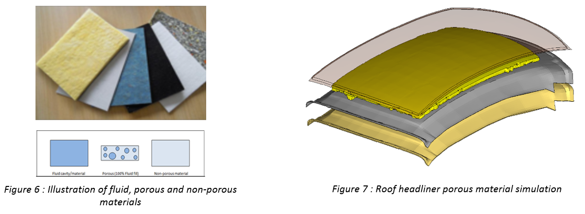
Trim Porous Material RepresentationA vehicle body includes many materials that are porous in nature, these include trim items, foams and carpets etc. These materials cannot be accurately modelled without accounting for the influence of the air spaces on the mechanical response, as illustrated in Figure 6.
Porous materials are implemented using Biot poroelastic theory applied to solid element representation. In this study, investigations were limited to representation of the headliner, shown in Figure 7.
Results
To assess the effect of modelling the physical effects of manufacturing and assembly, a driving point and vibration transfer function analysis of the trimmed body model was carried out. To assess the effect of trim porous materials, a noise transfer function analysis of the trimmed body model was also carried out.
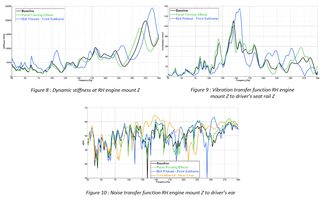
Figure 8 shows RH engine mount attachment dynamic stiffness in Z direction. Figure 9 shows the vibration response at the driver’s seat rail position due to excitation at the RH engine mount.
Figure 10 shows the noise response at the driver’s outer ear position due to excitation at the RH engine mount.
Attachment point dynamic stiffness and VTF predictions show significant change when physical effects due to manufacturing and assembly are considered in the simulation. NTF predictions also show significant change when porous material behaviour of trim is considered.
Panel thickness distribution changes due to panel forming was found to have the largest effects on dynamic stiffness above 150Hz, likely due to local panel resonance in this frequency region.
Bolt preload and contact was found to have significant effects on attachment point dynamic stiffness over the complete frequency range. Bolt preload and contact was applied only to the front sub-frame attachments. Consideration of preload and contact at all body bolted joints would be expected to modify dynamic performance even further.
Modelling of porous trim material was found to significantly change noise predictions above 60Hz. Porous materials have been considered only for the roof headliner. Including Biot material behaviour representation for all acoustic trim would be expected to modify noise predictions even further.
Results were compared for only one attachment. The combination from all attachments with consideration of physical effects due to manufacturing and assembly and porous material behaviour would be expected to have significant effect on vehicle level overall dynamic performance and hence NVH CAE predictions.
We’ll be wrapping up this series with a post on one last way to improve NVH prediction capabilities.
Spoiler alert! You can download the full paper here.

