New Altair SimSolid design studies
The primary goal of design-analysis is to evaluate the effect of design changes on the product’s performance. This needs to be done quickly and completely – at the “speed of design”. Most embedded CAD system analysis today are limited to simple part analyses and don’t allow easy comparison of different design configurations. Evaluating changes to a large assembly is particularly problematic. Altair SimSolid has a better way to set up and manage design studies. Read on to find out what Altair SimSolid design studies are and how they are unique.
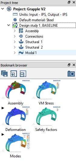
When a project is created, the initial CAD assembly is placed in a special BASELINE design study . This study acts as the reference to manage and evaluate design change. To establish the baseline, create one or more analyses, run them and save key result views with the bookmark browser as shown.
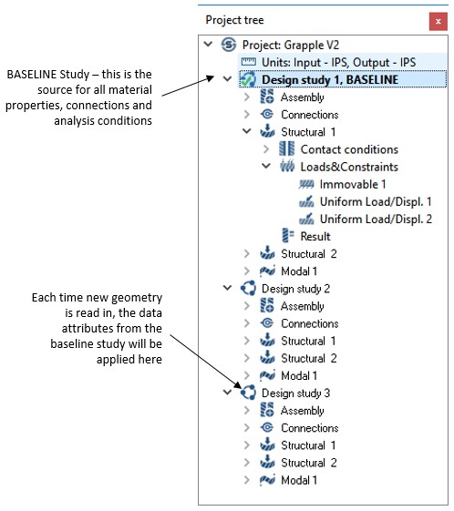
OK, we now have a baseline study, so how do we evaluate change? This can be done in a couple of ways. Every time modified design geometry is imported, it is automatically placed into a new design study and Altair SimSolid will reapply existing baseline material property, connection and analysis definition data. As an alternative, you can simply copy the design study then manually adjust geometry and connection data. This second method is useful if situations where you want to evaluate non-geometric changes such as suppressing parts, variations in material properties or adjustments to connection tolerances.
Make your design changes in SOLIDWORKS, then simply select the “Open in Altair SimSolid” button on the add-in panel. This will transfer the current active assembly to Altair SimSolid. A new dialog allows you to specify which Project to add it to. Each transfer will place the active SOLIDWORKS geometry into a new Altair SimSolid design study.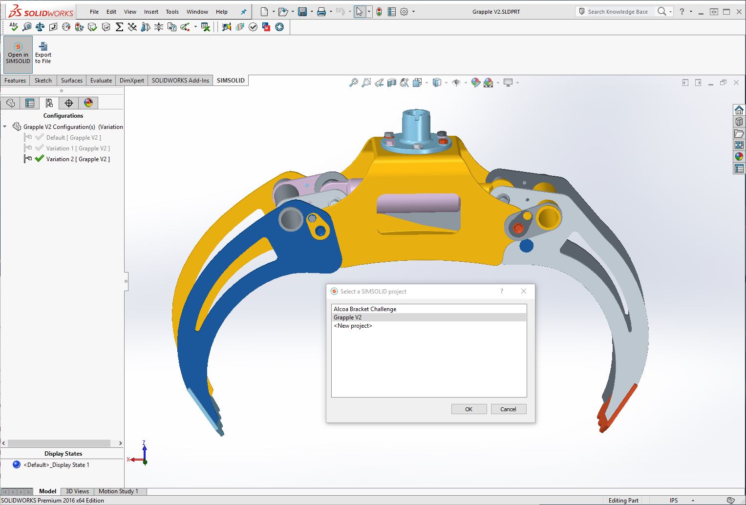
Getting geometric updates from Onshape or STL is even easier. From within the current Altair SimSolid Project, select either the “Import from cloud” (Onshape) or “Import from file” (STL) buttons on the main toolbar and browse to select the desired geometry to import. Each import is placed in a new Design Study branch of the Project tree.
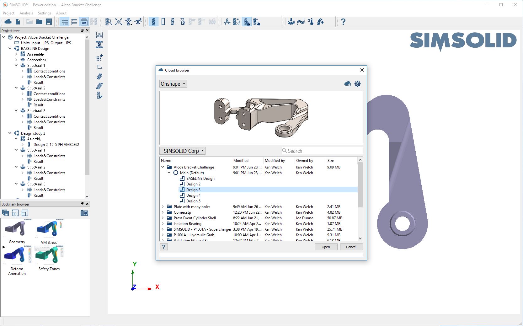
Note that you can easily mix and match between different CAD sources. One Altair SimSolid Project can have CAD data from Onshape, SOLIDWORKS and STL.
All red entities must be resolved before the new analysis can be started. For connections and contact conditions, Altair SimSolid will use automatic settings to reapply missing connections. Review to make sure this is what you want. Either, select using the right mouse button (RMB), then pick “Accept contact condition(s) in red” or double-click to Edit.
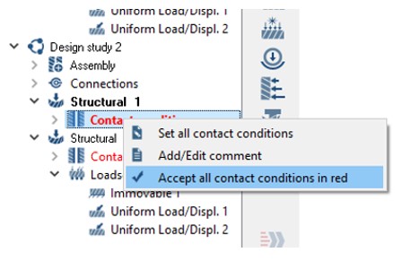 For boundary conditions in red, simply double-click to open the definition dialog and reselect the missing location (face, edge, spot, etc.). If the current selection is still appropriate, simply select OK to approve the change. The red will be removed and the new analysis can be started.
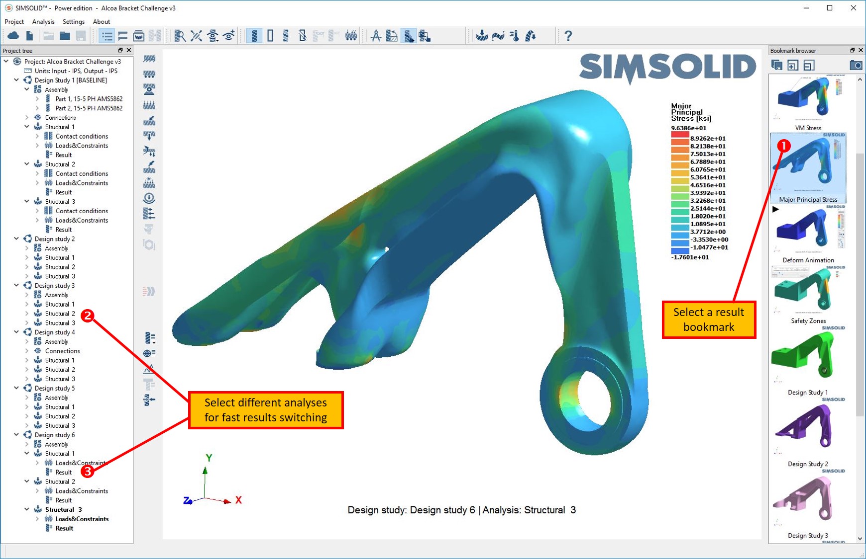
Fast results switching can be used to compare results from two different design studies. First, display an analysis result, such as a safety plot, contour plot or deform animation, in the graphics window. This can be done from either a saved bookmark (shown below) or from the results plot icon on the analysis workbench toolbar. Then, pick on another analysis in the project tree. The graphics window will instantly update its display to the new geometry and analysis results. Switch back and forth as quickly as you want.
Altair SimSolid design studies
A design study measures the impact of geometry or load condition changes on the performance of a structure. In Altair SimSolid, designs studies are defined as a set of part geometry, part connections and one or more analysis definitions along with their corresponding analysis results. Each design study can contain a complete CAD assembly containing hundreds of parts and each Altair SimSolid project can contain many design studies.When a project is created, the initial CAD assembly is placed in a special BASELINE design study . This study acts as the reference to manage and evaluate design change. To establish the baseline, create one or more analyses, run them and save key result views with the bookmark browser as shown.
OK, we now have a baseline study, so how do we evaluate change? This can be done in a couple of ways. Every time modified design geometry is imported, it is automatically placed into a new design study and Altair SimSolid will reapply existing baseline material property, connection and analysis definition data. As an alternative, you can simply copy the design study then manually adjust geometry and connection data. This second method is useful if situations where you want to evaluate non-geometric changes such as suppressing parts, variations in material properties or adjustments to connection tolerances.
Sources for design data
Updating design study geometry is very easy and can be done using either the familiar “push” (from SOLIDWORKS) or “pull” (from Onshape or STL) methodology.Make your design changes in SOLIDWORKS, then simply select the “Open in Altair SimSolid” button on the add-in panel. This will transfer the current active assembly to Altair SimSolid. A new dialog allows you to specify which Project to add it to. Each transfer will place the active SOLIDWORKS geometry into a new Altair SimSolid design study.
NOTE: only the changed part geometry is actually copied. All unchanged parts will be referenced from the previous studies. In this way, many design studies can be efficiently handled in a single Altair SimSolid project.
Getting geometric updates from Onshape or STL is even easier. From within the current Altair SimSolid Project, select either the “Import from cloud” (Onshape) or “Import from file” (STL) buttons on the main toolbar and browse to select the desired geometry to import. Each import is placed in a new Design Study branch of the Project tree.
Note that you can easily mix and match between different CAD sources. One Altair SimSolid Project can have CAD data from Onshape, SOLIDWORKS and STL.
Most importantly, loads and boundary conditions can be reapplied no matter what the source of the geometry change is. This generalization of analysis model associativity is very powerful and makes Altair SimSolid rapid design-analysis versatile to use.
Analysis model associativity
So what happens to my analysis definitions when I want to make a design change? No problems here - every time updated geometry is imported, it is placed into a new design study and Altair SimSolid will reapply existing baseline material property, connection and analysis definition data. With only a few exceptions, all analysis entities are supported. Even so, there are instances where mapping may be ambiguous. Any items that cannot be reapplied will be marked in red.All red entities must be resolved before the new analysis can be started. For connections and contact conditions, Altair SimSolid will use automatic settings to reapply missing connections. Review to make sure this is what you want. Either, select using the right mouse button (RMB), then pick “Accept contact condition(s) in red” or double-click to Edit.
For boundary conditions in red, simply double-click to open the definition dialog and reselect the missing location (face, edge, spot, etc.). If the current selection is still appropriate, simply select OK to approve the change. The red will be removed and the new analysis can be started.
 Comparing results
Fast results switching can be used to compare results from two different design studies. First, display an analysis result, such as a safety plot, contour plot or deform animation, in the graphics window. This can be done from either a saved bookmark (shown below) or from the results plot icon on the analysis workbench toolbar. Then, pick on another analysis in the project tree. The graphics window will instantly update its display to the new geometry and analysis results. Switch back and forth as quickly as you want.
Updating the baseline
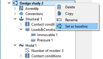
Once an improved design is found, the BASELINE reference can be reassigned and any studies that are no longer needed can be deleted.
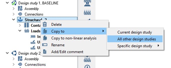
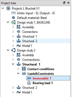
Copying analyses
While design studies automate the application of analysis boundary conditions, this can be done manually as well. Want to add one more analysis to all design studies? Simply add the analysis to one and then copy it to the others using a convenient right mouse button (RMB) function as shown.