Creating spot welds in Altair SimSolid
Spot welding is a common manufacturing technique to connect sheet metal parts in an assembly. While the process to create the physical weld is well understood, the methodology to model it for analysis is not. Traditional FEA systems require a variety of specialty elements with varying material properties and specific mesh transitions around weld areas. Many application specific approximations are used and the process to create the weld connection is tedious and error prone.
In Altair SimSolid, weld definitions are much simpler. Since only 3D solid geometry is used, spot welds can be placed directly on the model and only require a single parameter for the spot diameter. Laser welds are defined in a similar manner. Only width and line geometry are required.
Now select the weld type (spot or laser) and then the method to place the weld on the model. For spot welds, two methods are available – either a single spot weld or a series of spot welds placed along a line segment.
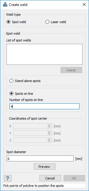
Pick the appropriate location on the model, enter the spot diameter and pick “Preview”. If the location and diameter are acceptable, pick OK to complete the definition.
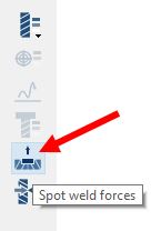
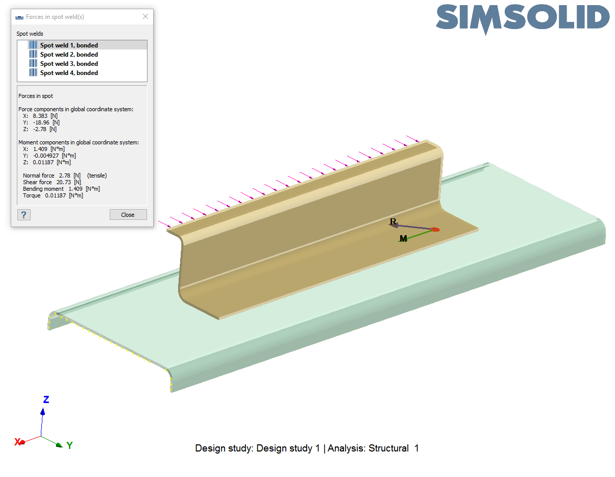
To view these forces, select the “Spot weld forces” button in the structural workbench toolbar.
 Then simply pick a spot weld to view its resultant normal force, shear force, bending moment and torque.
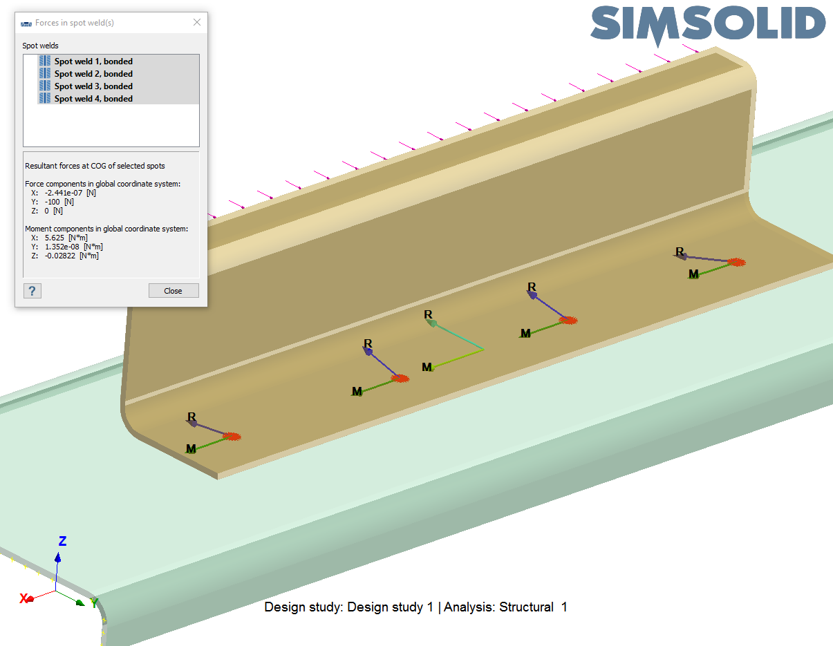
As an alternative, CTRL-Select and SHIFT-Select multiple values to sum the forces and moment contributions. An additional set of vector will show the location and direction of the summed forces.
Modeling spot welds have ever been easier. Go ahead and give them a try.
In Altair SimSolid, weld definitions are much simpler. Since only 3D solid geometry is used, spot welds can be placed directly on the model and only require a single parameter for the spot diameter. Laser welds are defined in a similar manner. Only width and line geometry are required.
Spot weld definition
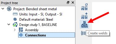
To create a spot weld, do the following. First select the “Create welds” icon in the Connections toolbar.
Now select the weld type (spot or laser) and then the method to place the weld on the model. For spot welds, two methods are available – either a single spot weld or a series of spot welds placed along a line segment.

Pick the appropriate location on the model, enter the spot diameter and pick “Preview”. If the location and diameter are acceptable, pick OK to complete the definition.
How to post-process
In Altair SimSolid, spot weld location is defined on the actual faces of 3D sheet metal. No need to model the offsets. This is the basis for accurate spot weld force predictions including torque, shear and bending.To view these forces, select the “Spot weld forces” button in the structural workbench toolbar.
 Then simply pick a spot weld to view its resultant normal force, shear force, bending moment and torque.
As an alternative, CTRL-Select and SHIFT-Select multiple values to sum the forces and moment contributions. An additional set of vector will show the location and direction of the summed forces.

Where can I find out more?
Altair SimSolid comes in three editions, Standard, Power and Professional. All weld capabilities, including spot, laser and fillet welds, are available in the Professional edition only. More information on each product edition can be found here.Modeling spot welds have ever been easier. Go ahead and give them a try.


