
A Workflow for Fatigue Analysis of Solder Joints in PCB Under Vibrational Loading
The trend towards the electrification of vehicle drives requires the development of electronic components that can withstand multiple types of loads, e.g., static, dynamic, and thermal-mechanical loads. One great challenge here is the reliability assessment of printed circuit board assemblies (PCBAs) by finite-element analyses (FEAs), because the PCBA geometry is usually really complex and the resulting computational effort in the FEAs is therefore huge. The geometrical complexity is caused by the details of a PCB layout, which is defined by multiple layers of copper traces and hundreds or even thousands of vias, and the vast number of surface mounted devices and solder joints. The computational effort is a result of the geometrical complexity, i.e., leading to detailed finite element models of solder joints, copper traces and vias.
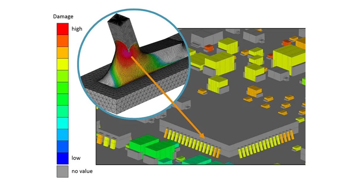
In this talk we present our state-of-the-art simulation processes for the structural reliability analysis of PCBAs and we show how these processes benefit from FEA process automation. The highlights of the FEA process automations are the automatic generation of detailed solder joint FE-models, the automatic generation of detailed FE-models of PCBs based on ECAD-data, and sub-modeling, sub-structuring, and material-homogenization techniques for the reduction of the computational effort in the FEAs.
Featuring FEMFAT by Magna Engineering Center Steyr, available through the Altair Partner Alliance.