

The Brennan’s Last Stand: Optimizing a Tree Stand that will Last with Altair Inspire
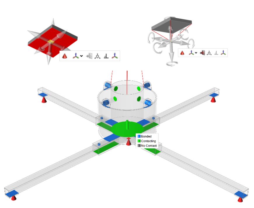
Before the holidays, I shared the process of analyzing my family’s Christmas Tree stand as an example of using Inspire as a FEA tool. The loads and supports that I found to be the most realistic can be seen in the models below, if you’d like to read how I decided on those conditions, see my previous post. In this blog, I will explore how I used those boundary conditions and Inspire’s optimization tools to create a bracket to further strengthen the tree stand.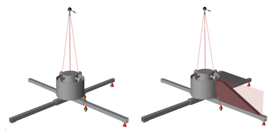
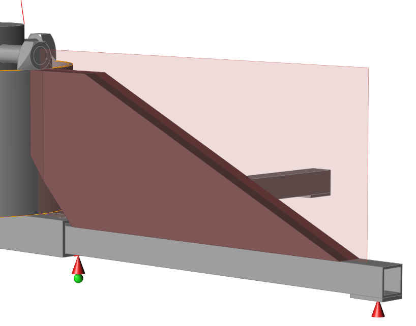
The first step towards running an optimization (after defining realistic boundary conditions) is to create a design space (DS) for the optimization to take place. Initial design spaces are usually very large, overdesigned and defeatured parts that encapsulate the entire volume that the optimized part could exist to allow Inspire as much space as possible to create the optimized shape. In the case of the Christmas Tree stand model, the most obvious DS is some form of a bracket that extends from the bolt securing the tree in place down to the leg to provide some extra strength and relieve stress from the bolt area. I created the initial DS for this model so that it would connect to the current design with bolts in the leg and the bowl; that way it can be removed for storage like the legs. I also assigned a symmetry plane to the DS so the generated shape symmetry constraint about the plane seen in red. In general, it is good practice to run an initial optimization that is free of manufacturing constraints to discover the true load path. I will use this free result for the remaining analysis however, Inspire does have the capability of generating optimized shapes that are specifically designed for casting, molding, extrusion and additive manufacturing.
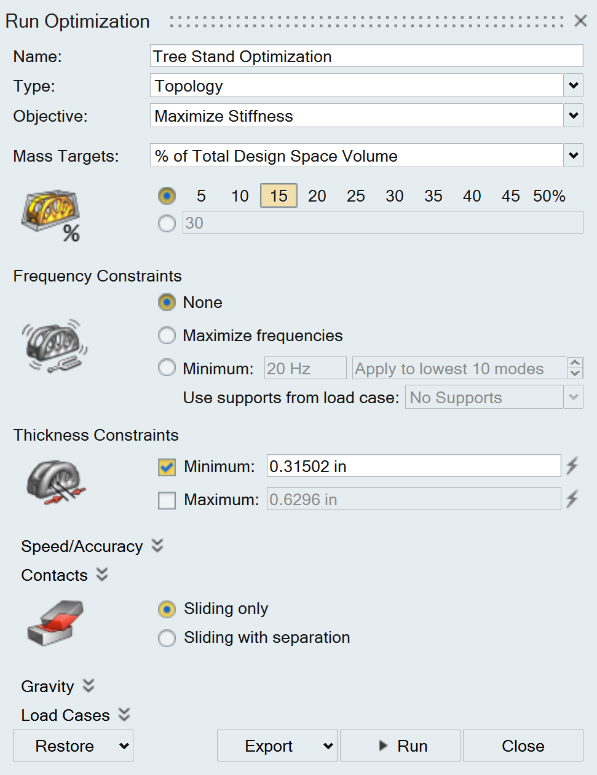
After the DS is created and ready for optimization, the Run Options must be specified. For the purposes of this model, I want to maximize the stiffness of the bracket that is created so we will use Topology optimization and Maximize Stiffness as the objective; this provides the stiffest possible result for a given mass target. For this initial run, I’ll set the mass target at 15% and use the Thickness Constraints that are suggested by Inspire. Decreasing the minimum thickness will increase the resolution of the resulting shape but also increase the run time.
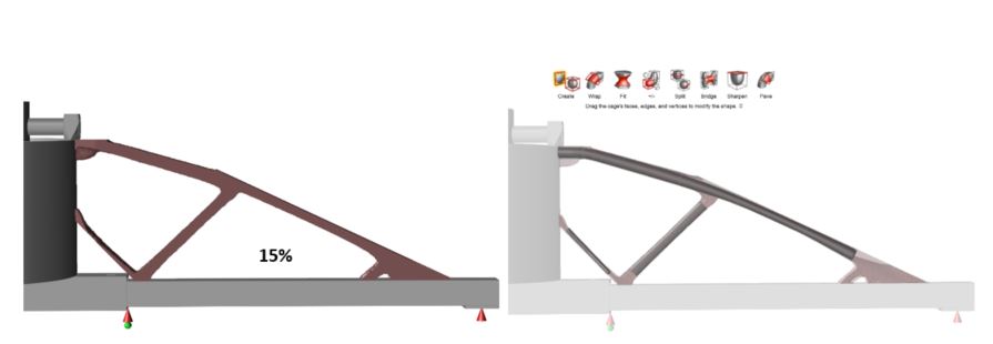
The results from this run are seen above. For further analysis, I will use this 15% result and the polyNURBS tools to generate a smoother shape. Within polyNURBS there are many different tools for generating smooth shapes. Wrapping optimization results with NURBS is an easy way to quickly build pieces of the model that are then connected. After using the various polyNURBS tools, I came up with the shape below. The whole polyNURBS process took about 15 minutes to generate and now I have a smooth surface with holes for bolts and geometry that can be exported for manufacturing.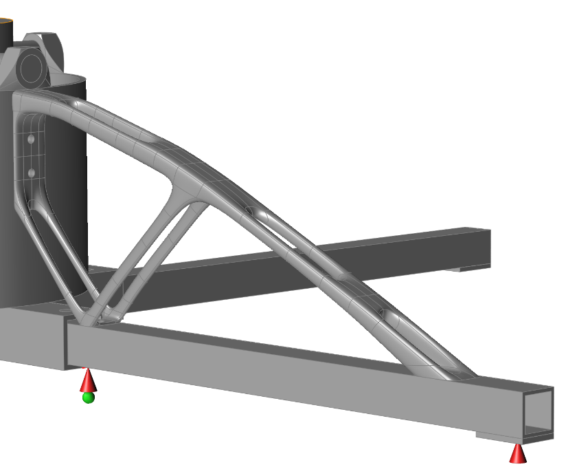
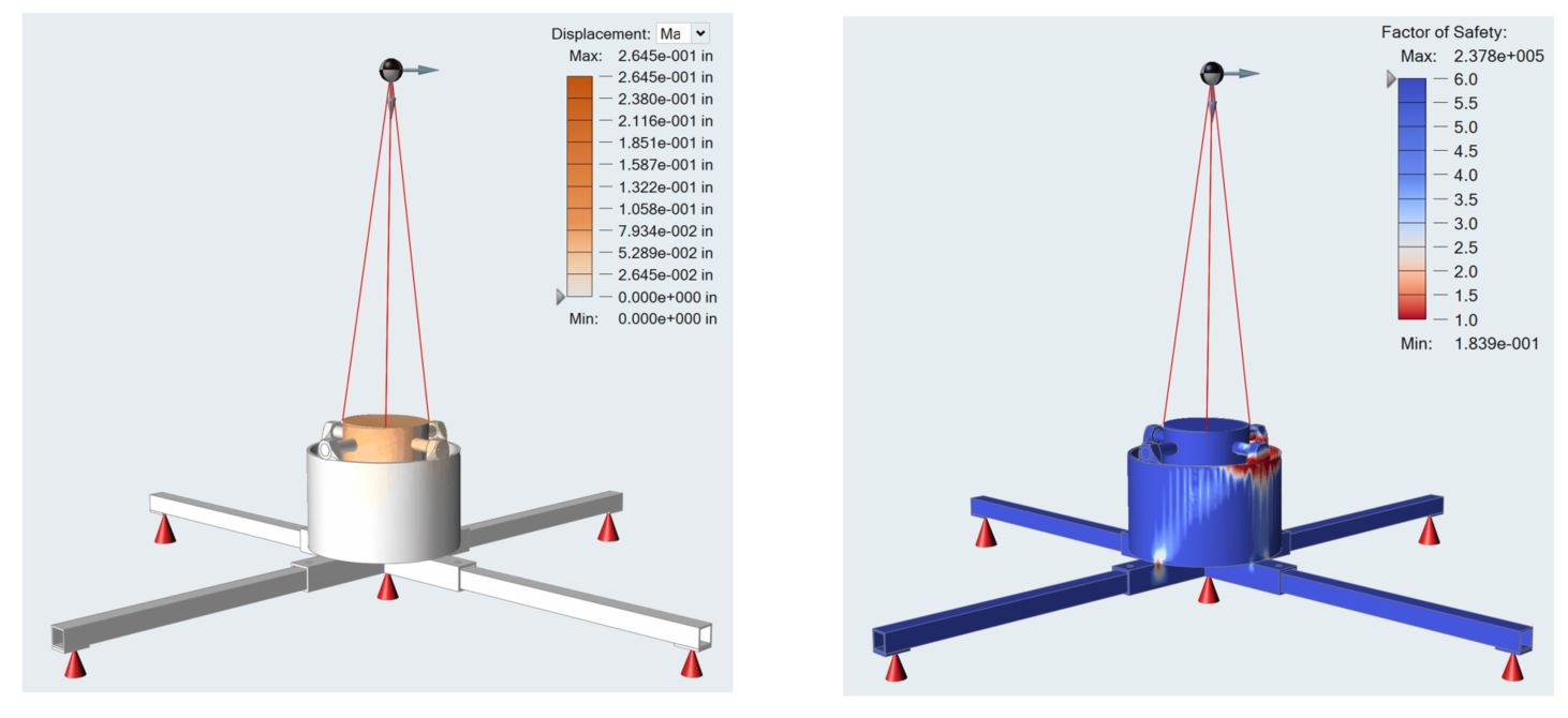
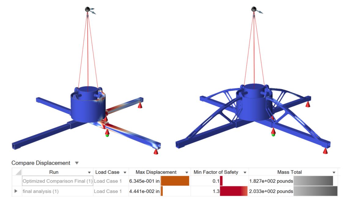
In a direct comparison, the added strength of the optimized bracket clearly removes most of the high stress areas from the original model at the cost of only 5 pounds per bracket, less than that of the arms of the stand (20.6 lbs total). You can see from the results below that the addition of the bracket reduces the maximum displacement by 93% and increase the minimum factor of safety from 0.1 to 1.3.
Despite being relatively lightweight, this bracket is quite large due to the design space that I defined in the beginning. One of the main features of Inspire is the ability to quickly and easily iterate through different designs and conditions and further optimize your design. In the same amount of time it took me to design and fully analyze this part, I could go back and edit the original DS to a different shape or design constraint, run an optimization, use polyNURBS, analyze and compare an entirely different design to the first run and the original model. In addition, as previously mentioned, I could use the manufacturing shape controls to designate the part to be cast, extruded, or 3D printed and generate different results then use the Inspire manufacturing tools (Cast, Extrude, From, etc.) to simulate the desired manufacturing process. That is truly where the power of Inspire is unleashed; when used as a robust FEA tool to define proper loads and constraints then using those conditions and iterating quickly through many different design ideas until the best option is discovered. Coupled with the manufacturing simulation tools, the Inspire platform provides end-to-end design and simulation tools that can be quickly learned and used by anyone.