

Apples to Apples, not Apples to Oranges
Many people that try Altair SimSolid for the first time want to understand how it compares to well know reference solutions. A common comparison are beam models. There are many references available and the theoretical values are easy to hand calculate.
While these studies are simple to do in Altair SimSolid, care must be taken to properly account for the boundary conditions. What many think are “Apples to Apples” comparisons are in fact not the case.
For example, consider a simply supported beam, pinned at both ends and loaded in the middle.
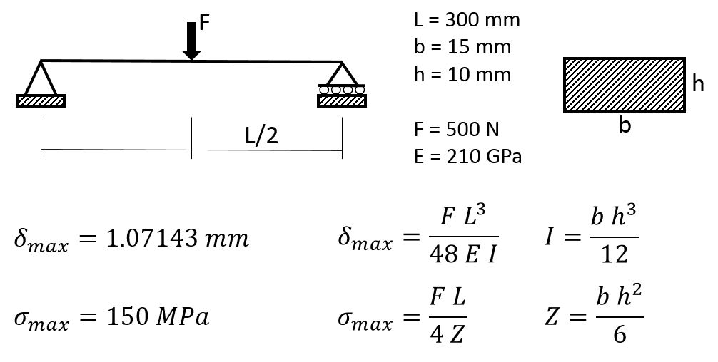
The reference solution (shown above) is based on beam theory. There are two major assumptions in the theory – when the beam bends, the middle surface of the beam does not stretch and flat cross-sections of the beam remain flat and normal to the deflected middle surface. These assumptions allows us replace the 3D solid beam with a 1D beam and derive nice engineering formulas to evaluate deflections and stresses in the beam. But these formulas assume that beam constraints are applied to the 1D model which is the neutral axis of the beam, and top and bottom layers of the beam are fully free to stretch or compress when the neutral axis deflects.
Therefore, in order to do a meaningful comparison with Altair SimSolid, care must be taken to constrain the beam at the mid-surface and not the beam bottom or top. To properly model this in Altair SimSolid, line “Spots” can be used to define both the mid-surface end constraint locations as well as the mid-beam load location. Spot lines are rectangles with one edge set to zero as shown.
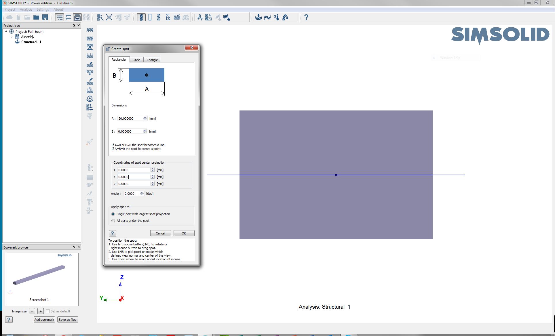
To make the model simply supported, we apply an immovable constraint to one end spot line and a specified zero Z (vertical) displacement at the other.
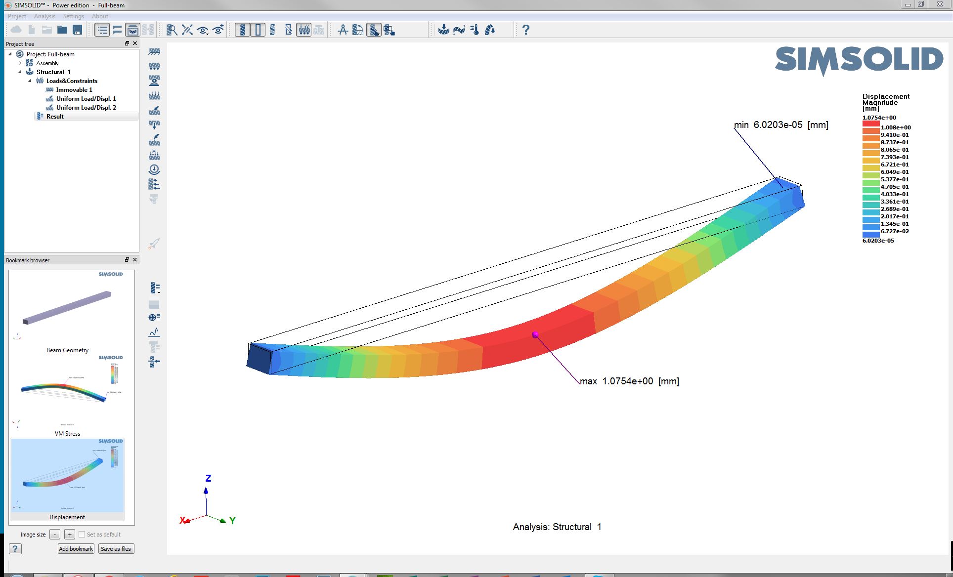
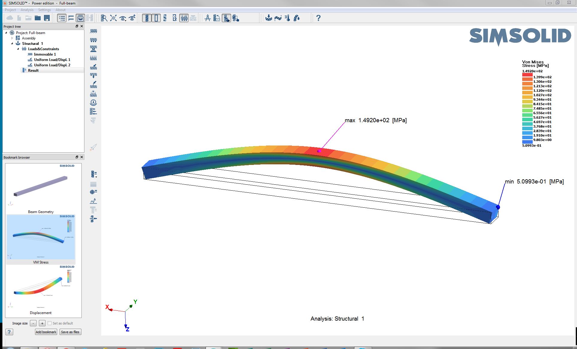
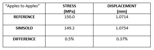
Now just apply a downward 500 N load at the mid-beam line spot and run the analysis. Altair SimSolid’s default adaptive solution settings gives deflection and stress results that are extremely close to the reference solution, though they are obtained in a complete 3D solid formulation.
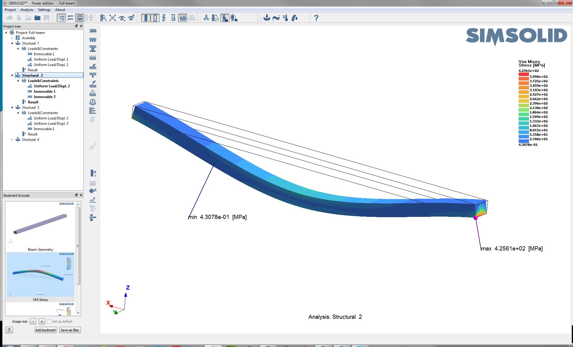
To illustrate this point, in the following we keep the load the same but apply immovable constraints to the bottom edges at each end.

As can been seen, the beam is no longer simply supported. The model is now over constrained. The maximum displacement is cut in half and the maximum stress is much greater. Now we have local stress concentrations near the constrained edges and the key solution values are much different from those in the reference beam solution.
Comparing numerical and theoretical solutions are not always straightforward. Challenges come from the simplifying assumptions made in the theoretical derivations as compared to the Altair SimSolid full 3D solution methods. Care must be taken to ensure that the boundary conditions relate to the theoretical assumptions made.
For more information on comparing Altair SimSolid with reference solutions, please see our Verification manual. It can be downloaded from Altair Connect.
While these studies are simple to do in Altair SimSolid, care must be taken to properly account for the boundary conditions. What many think are “Apples to Apples” comparisons are in fact not the case.
For example, consider a simply supported beam, pinned at both ends and loaded in the middle.
The reference solution (shown above) is based on beam theory. There are two major assumptions in the theory – when the beam bends, the middle surface of the beam does not stretch and flat cross-sections of the beam remain flat and normal to the deflected middle surface. These assumptions allows us replace the 3D solid beam with a 1D beam and derive nice engineering formulas to evaluate deflections and stresses in the beam. But these formulas assume that beam constraints are applied to the 1D model which is the neutral axis of the beam, and top and bottom layers of the beam are fully free to stretch or compress when the neutral axis deflects.
Therefore, in order to do a meaningful comparison with Altair SimSolid, care must be taken to constrain the beam at the mid-surface and not the beam bottom or top. To properly model this in Altair SimSolid, line “Spots” can be used to define both the mid-surface end constraint locations as well as the mid-beam load location. Spot lines are rectangles with one edge set to zero as shown.
To make the model simply supported, we apply an immovable constraint to one end spot line and a specified zero Z (vertical) displacement at the other.
Now just apply a downward 500 N load at the mid-beam line spot and run the analysis. Altair SimSolid’s default adaptive solution settings gives deflection and stress results that are extremely close to the reference solution, though they are obtained in a complete 3D solid formulation.
Sounds easy, so what can go wrong?
The most common mistakes are not constraining the model at the neutral axis or not making the part simply supported. Altair SimSolid always does a full 3D solution and small changes can have dramatic effects. This often leads to an “Apples to Oranges” comparison where you may not get the results you expect.To illustrate this point, in the following we keep the load the same but apply immovable constraints to the bottom edges at each end.
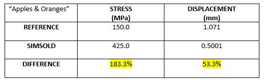
As can been seen, the beam is no longer simply supported. The model is now over constrained. The maximum displacement is cut in half and the maximum stress is much greater. Now we have local stress concentrations near the constrained edges and the key solution values are much different from those in the reference beam solution.
Comparing numerical and theoretical solutions are not always straightforward. Challenges come from the simplifying assumptions made in the theoretical derivations as compared to the Altair SimSolid full 3D solution methods. Care must be taken to ensure that the boundary conditions relate to the theoretical assumptions made.
For more information on comparing Altair SimSolid with reference solutions, please see our Verification manual. It can be downloaded from Altair Connect.