How to create a bolt load in Altair SimSolid
In traditional FEA, there are many approaches to simulate bolt loading. Most of them are based on the idea of bolt shank shrinkage. The shrinkage creates the force applied to parts which are connected to the bolt. The bolt itself usually is simulated by bar elements with "spider" rods connecting ends of the bar with contact areas under bolt head and nut.
In Altair SimSolid, bolts and nut loads are always simulated as a solid body. Bolt loading is simulated as it happens in real life - through bolt tightening. The tightening is defined using the common “turn-of-nut” method. This method rotates the nut or bolt of a fastener by a specified turn angle past its snug configuration. In terms of mechanics, displacement of the nut relative to the bolt shank is prescribed. The result is that when the bolt is tightened, the shank elongates, not shrinks. Therefore, this approach is very "physical", it does not use an artificial concept of shank shrinkage which provides less accurate results.
 Note that in Altair SimSolid, bolts and nuts are automatically identified by examining geometric attributes and may not be specified manually. A bolt must have a cylindrical shank and a hexahedral shaped head. The hex pattern can be on the outer or inner diameters of the head. A nut is optional, but if present, must have a hex pattern as well. If a nut is not found, the bolt will assume to be blind with a threaded connection in the last part that it penetrates. Nuts can exist without bolts but must be associated to another cylindrical shaped part such as a rod, post or handle.
In Altair SimSolid, bolt or nut loads can be applied in a variety of configurations including:
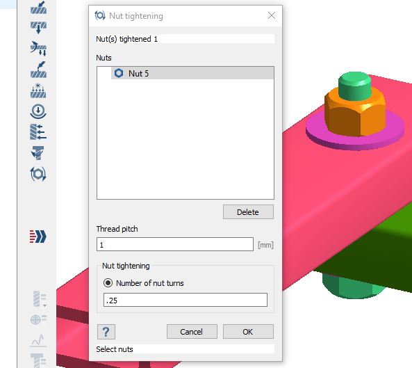
For bolts with nuts or nuts on a threaded rod, open the Nut tightening dialog and do the same thing. Select one or more nuts and then specify the thread pitch and turn amount. The bolt load is specified in Altair SimSolid by imposing a displacement, D, of the nut or of the tapped hole relative to the bolt shank length: D = <pitch> * <number of turns>
To calculate the bolt forces, apply a simply supported constraint and run a static analysis. Once complete, you can examine bolt deformation and stresses using standard result contours and animation plots.
[video width="1344" height="944" mp4="https://www.simsolid.com/wp-content/uploads/2016/05/bolt-deform-animation.mp4" loop="true" autoplay="true"][/video]
In Altair SimSolid, bolts and nut loads are always simulated as a solid body. Bolt loading is simulated as it happens in real life - through bolt tightening. The tightening is defined using the common “turn-of-nut” method. This method rotates the nut or bolt of a fastener by a specified turn angle past its snug configuration. In terms of mechanics, displacement of the nut relative to the bolt shank is prescribed. The result is that when the bolt is tightened, the shank elongates, not shrinks. Therefore, this approach is very "physical", it does not use an artificial concept of shank shrinkage which provides less accurate results.
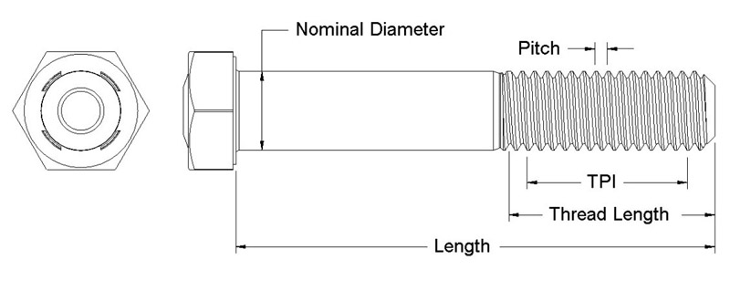
Some quick terminology
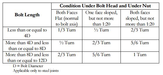
Bolts are commonly defined by length, diameter and thread pitch. In the following, thread Pitch and bolt turns are used to specify the bolt tightening load. The amount of prescribed turn is dependent on the bolt Length to Nominal Diameter ratio.Note that in Altair SimSolid, bolts and nuts are automatically identified by examining geometric attributes and may not be specified manually. A bolt must have a cylindrical shank and a hexahedral shaped head. The hex pattern can be on the outer or inner diameters of the head. A nut is optional, but if present, must have a hex pattern as well. If a nut is not found, the bolt will assume to be blind with a threaded connection in the last part that it penetrates. Nuts can exist without bolts but must be associated to another cylindrical shaped part such as a rod, post or handle.In Altair SimSolid, bolt or nut loads can be applied in a variety of configurations including:
- Blind bolts
- Bolts with nuts
- Nuts on threaded rods (one or both ends)
- Nuts on a threaded post or handle.
- Multiple nuts on the same bolt or threaded post
Creating a bolt or nut tightening load
To create a bolt load in Altair SimSolid do the following. For blind bolts (those without nuts), open the bolt tightening dialog, select one or more bolt parts in the model then specify the bolt thread pitch and the turn angle. Note that the angle is specified as fractional bolt turns and not degrees or radians. For example, a value of 0.5 represents a nut turn angle of 180-degrees.For bolts with nuts or nuts on a threaded rod, open the Nut tightening dialog and do the same thing. Select one or more nuts and then specify the thread pitch and turn amount. The bolt load is specified in Altair SimSolid by imposing a displacement, D, of the nut or of the tapped hole relative to the bolt shank length: D = <pitch> * <number of turns>
To calculate the bolt forces, apply a simply supported constraint and run a static analysis. Once complete, you can examine bolt deformation and stresses using standard result contours and animation plots.
[video width="1344" height="944" mp4="https://www.simsolid.com/wp-content/uploads/2016/05/bolt-deform-animation.mp4" loop="true" autoplay="true"][/video]
Nut turning is visualized during deformation animation. Note that the bolt deformation is false scaled but the twist of the nut is the actual turn amount.
How much bolt load to apply?
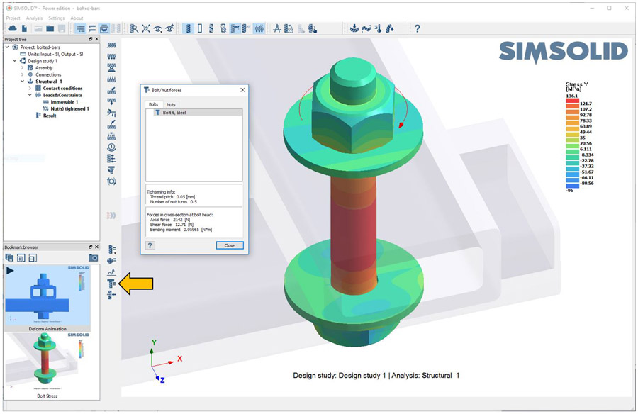
One common rule of thumb is to load the bolt to 70% of its tensile strength. In Altair SimSolid, you can visualize the bolt load in a number of ways. To look at the bolt forces, open the Bolt/nut result loads dialog and pick either a bolt or nut as shown. As an alternative, use a normal stress plot to view the cross-sectional stress in the bolt, or use the Safety zone plot to view the failure criterion in the bolt.
Bolt/nut forces dialog is found in the results toolbar as shown. Bolt axial stress shown with other parts hidden.