

The Art of Map Meshing
As computer aided design (CAD) geometry has become more detailed, developing a finite element model to capture these features has required an increasing amount of time and experience. A tetrahedral mesh is often chosen because of its speed and robustness to discretize heavily featured geometry (e.g. hundreds of fillets). However, for structural analysis, tetrahedral elements can produce “stiff” results with an unacceptable percent error. For example, a modal analysis can produce higher than expected frequencies. To overcome this, mesh refinement and higher order tetrahedral elements can be used but this costs increased solve times and computational resources.
Another well-known approach to discretizing a model is “map meshing”, also known as solid meshing and hex meshing. For a given element size, its formulation does not have the issue of stiffness, it has faster solve times, and can produce results with less percent error. For all the advancements in processing automation, map meshing has not reached the level of automation like tet meshing has, leaving a large part of it to remain an art that is heavily dependent on user experience.
Nevertheless, map meshing can be helped by:
- Keeping the fundamental rules to map meshing in mind
- Heeding some general tips and tricks
- Utilizing the powerful tools in Altair HyperMesh™
The Golden Rules of Map Meshing
- Solid geometry source and destination faces need to be opposing
- Multiple faces may map to only one face
- No features may oppose the direction the mesh will be dragged
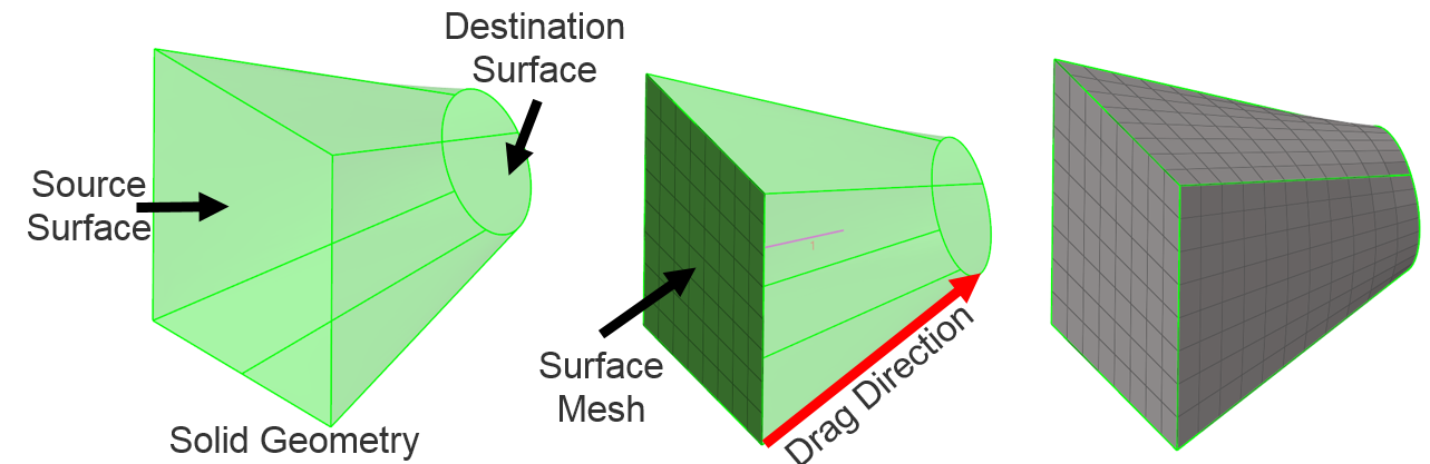
Figure 1: The Golden Rules for Map Meshing
The three “golden” rules can become harder to satisfy as a model is edited down into simpler geometries. Editing one section of a model may produce a topology feature that renders a once mappable section into an unmappable one. This is where processes and tools can help.
Visualizing Mappable Solids
Similar to topology visualization, Altair HyperMesh ™ has a specific visualization for mappable solids. This handy feature helps indicate, via color coding and transparency, how a solid is being interpreted for mappability and what steps should be taken next.
- Blue indicates a solid that needs to be edited (e.g. features removed)
- Orange is a solid that needs to be partitioned
- Yellow shows mappability in a single direction
- Green is the ideal color, as it is a solid which is mappable in any direction
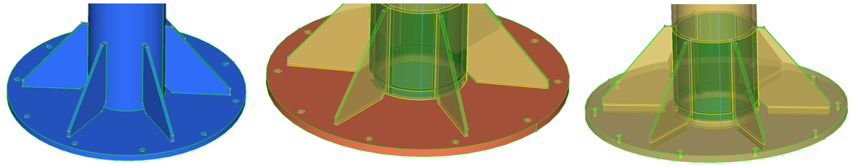
Figure 2: Mappable solids coloring
Partitioning Geometry with HyperMesh
The partitioning of geometry to produce mappable sections can be made easier with the following processes and HyperMesh features:
- Process: Defeature all unnecessary features of a model. For example, fillets that are a part of the assumed manufacturing processes (Figure 2). Remove features in areas that may not be an area of interest.
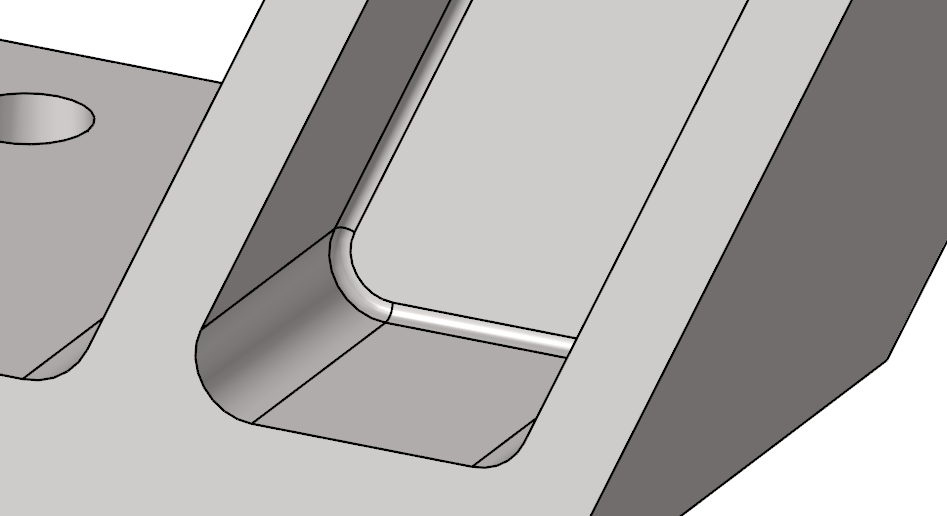
Figure 3: Consider defeaturing manufacturing features
- Process: If a model is symmetric, like a submarine hull, partition the model about its plane(s) of symmetry, map mesh, and then copy and reflect the mesh to generate the whole model (Figure 4).
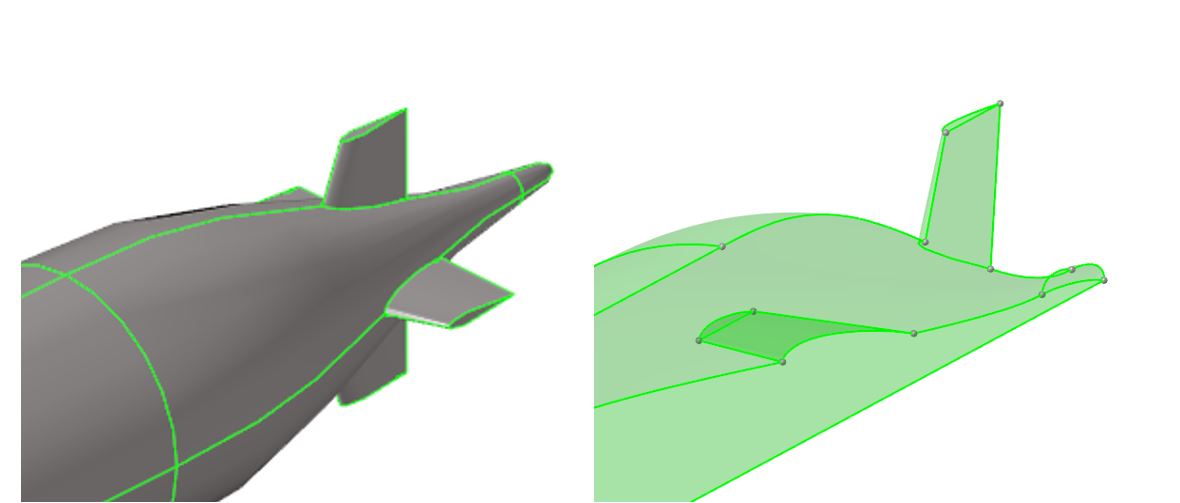
Figure 4: Submarine hull is an example of a model ideal for applying symmetry
- Process: Throughout partitioning save the model often with different names which describe the progress that has been made in partitioning. If one approach leads in a direction that is not helpful, a previous model may be used as a starting point. This also prevents any computer glitches or power outages from erasing a hard day’s work.
- Process: Utilizing the native topology of a model may not be enough to fully partition a model into mappable geometries. Keep an open mind to generating additional surfaces and lines and use these to edit the model. Store these in separator “collectors” with appropriate names.
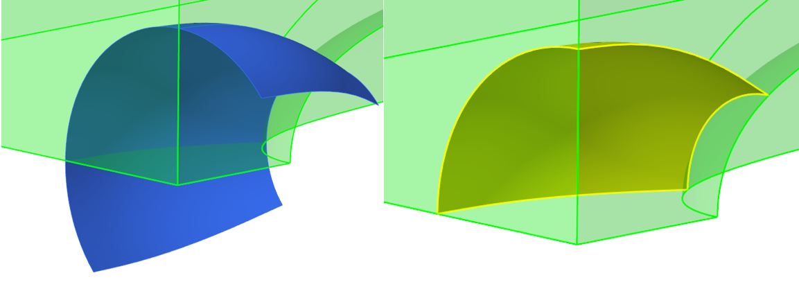
Figure 5: Partitioning with user created surface
- Feature: Adjust the “cleanup tolerance” in the Preferences > Geometry Options based on the feature being edited. A small tolerance can help produce very fine edits but can also create additional topology. A larger tolerance can collapse and bring very small topology features together. Applying this knowledge can help with successful partitioning.
- Feature: Switch between HyperMesh’s “By 3D Topo” and “Mappable” visualization. Often only one is utilized in the process of partitioning geometry – namely Mappable – but the former gives great insight into other features in the model aiding in understanding how future edits may affect the model.
- Feature: Often when geometry is imported into HyperMesh multiple solids are recognized but their shared surfaces are not. Boolean these geometries together such that their shared surfaces are recognized can help save time. Geometry > Edit > Solids Boolean (Advanced, A+B, combine through: none) is the specific tool.
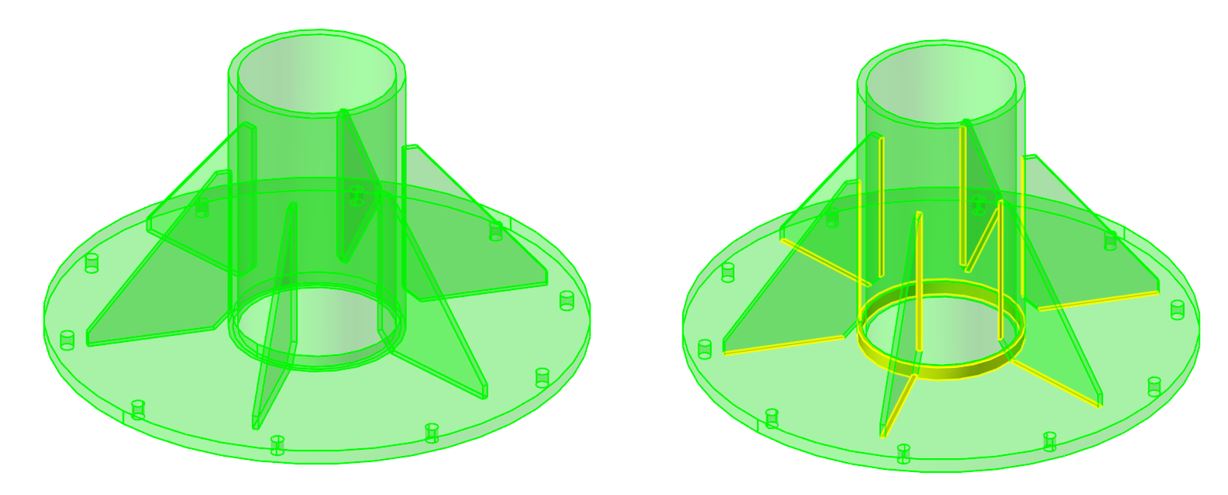
Figure 6: Utilize Boolean to quickly update shared surface topology
- Feature: A handy and often overlooked feature is the favorites icon
 in HyperMesh. Partitioning can be a very repetitive task, using only a half-dozen features, but navigating to them can greatly increase input tasks and time. The favorites will store the features in one location for quick access.
 - Feature: Knowing the shortcut keys can help reduce user input (i.e. keyboard and mouse clicking). The complete list can be found in HyperWorks documentation by searching for “HyperWorks Desktop Keyboard Functions.” For example, undo (CNTRL + Z) is a well-known keyboard combination and helps during the process of geometry editing. Another is the scroll wheel (middle button) click which will execute a feature and does not require clicking the green button in the HyperMesh panel.
Map Meshing with HyperMesh
The following processes and features can help with map meshing:
- Process: Have a thorough understanding of the model’s geometry and plan out the mapping of the mesh. Starting from one location may not produce the same results as starting from another.
- Process: Choose an element size based on the smallest feature (Figure 7). This element size will propagate through the model. Using the correct size will aid in the elements quality and count.
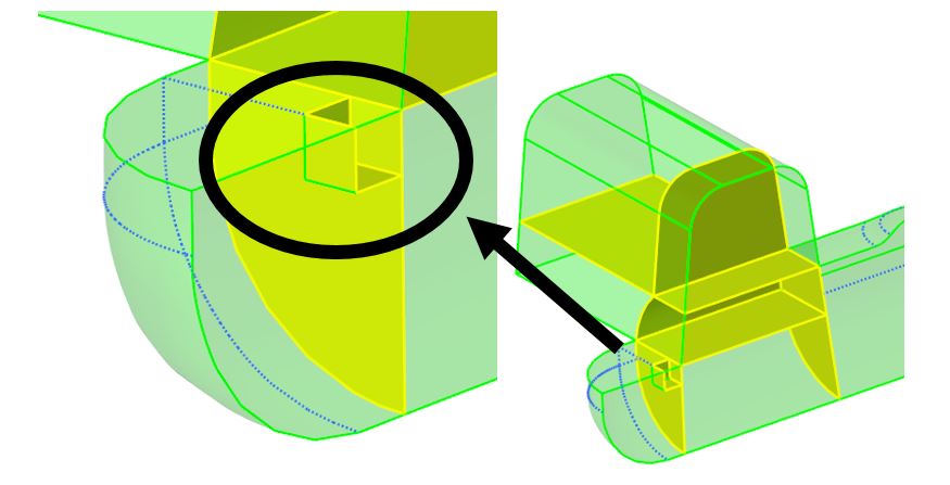
Figure 7: Choose element size based on smallest partition
- Process: Begin map meshing from the more complicated feature like a fillet or important curvature.
- Process: When creating a 2D mesh to map, keep in mind that a quad only mesh requires the perimeter element count to be an even number. Also, to generate a structured mesh the opposing edges must have the same nodal count.
- Process: When map meshing one partition at a time (i.e. using the general panel) confirm the mesh quality meets desired criteria Mesh > Check > Elements > Check Elements after each mapping.
- Feature: Adding or suppressing topology with Geometry > Quick edit > toggle edge: can help HyperMesh recognize a volume as mappable (Figure 8)
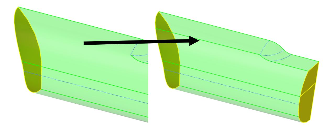
Figure 8: Adding topology to assist mapping
- Feature: If a mappable solid is not visualized as mappable, a manual update of the mappability can be executed via the Mesh > Create > Solid map mesh > multi solids
- Feature: “Mappable” visualization is on a solid by solid basis. In other words, just because a model’s partitions are visualized as mappable does not necessarily mean additional editing will not be required. Execute the “multi solids” feature to determine if the model is mappable.
- Feature: Although it is preferable to obtain a model that is visualized as mappable because the “multi solids” mapping feature may be used to quickly generate a mesh throughout all of the partitions, it is not absolutely necessary. The “general” panel may also be used to map mesh individual partitions with some additional user inputs.
- Feature: The map meshing panels have a number of warning messages or hints; a common one is “sequencing error.” This is an indicator that additional partitioning is necessary to help HyperMesh order the meshing of the solids.
- Feature: When duplicating and reflecting a mesh to generate a full model from a symmetry section always check nodal connectivity with Mesh > Check > Nodes > Equivalence with a tolerance less than the smallest element size.
Fine Tuning with HyperMorph in HyperMesh
Model redesigns are an integral part of the product development as performance results and requirements mature. What this means is multiple models will need to be meshed. For map meshing, this can be a headache as designers can quickly modify fillets, hole diameters, and plate thicknesses on a model that took a day or more to map for meshing.
HyperMorph is the unsung sidekick for map meshing because, for these relatively small adjustments. It allows for the movement of nodes (i.e. nodal perturbation) from one location, to a new one. The element quality is maintained as the perturbation is interpolated through the local elements. HyperMorph not only helps with redesigns but also design exploration like modifying the thickness of a component to see how it affects the performance.
Altair Connect™ has additional resources (e.g. tutorials) on HyperMorph capabilities, and future articles will further explore how it can assist map meshing.
Concluding Thoughts
Map meshing remains an important approach to discretizing a model due to its advantages of solution quality, solve time, and computational resources. With the application of the processes, tips, and powerful HyperMesh features, map meshing is more structured, approachable, and overall an enjoyable art.