
Large model analysis using Altair SimSolid
Why solve large models
In statics, analyzing large models provides the ability to evaluate complete load paths. This provides both a high-level overview of the project’s structural feasibility as well as insight where to do more detailed studies. In dynamics, analysis of complete assemblies is even more important as parts interact and any part removed in simplification changes mass and mass distribution which in turn affects frequencies and mode shapes.In the past with traditional FEA, the only practical option was to merge large multi-part assemblies into single lumped structures and then mesh and solve them in this aggregated form. This led to several problems. One, numerical convergence was difficult to ascertain. Adaptive analysis was not practical and the time to solution for a single meshing and solve step was significant. Second, merging led to many sharp geometric features that in turn caused artificial stress hot spots to occur. More often than not, lack of high performance computing (HPC) capacity meant structural analysis of large assemblies was not considered at all.
Using Altair SimSolid, analysis of large models is very practical. Model merging is never done, so the simulation is done on geometry that more closely represents the physical object. Adaptive analysis is always active, so numerical convergence is always considered. Options are available to enable an engineer to locally refine the numerical solution on a part or part feature level making it easy to drill in for more detail where necessary. Best of all, models are efficiently processed on standard low cost computers.
Altair SimSolid is redefining the state-of-the-art for what is considered possible and practical for large assembly structural analysis
As a case in point, we will consider the steps necessary to model and analyze a large rotating theater stage. Designed and manufactured by SBS Buehnentechnik in Dresden, Germany, the design requirements dictated that the stage remain stiff enough, but not too heavy, so that it can be moved and reconfigured without requiring huge motors. Insight on displacement sag from the dead load+gravity loads, floor level gaps occurring between rotating rings, and dynamic frequencies of the entire structure were desired. The structural steel frame model consisted of over 5,200 parts and two rotating stages. On top of this, a wooden floor panel with stringers was placed.
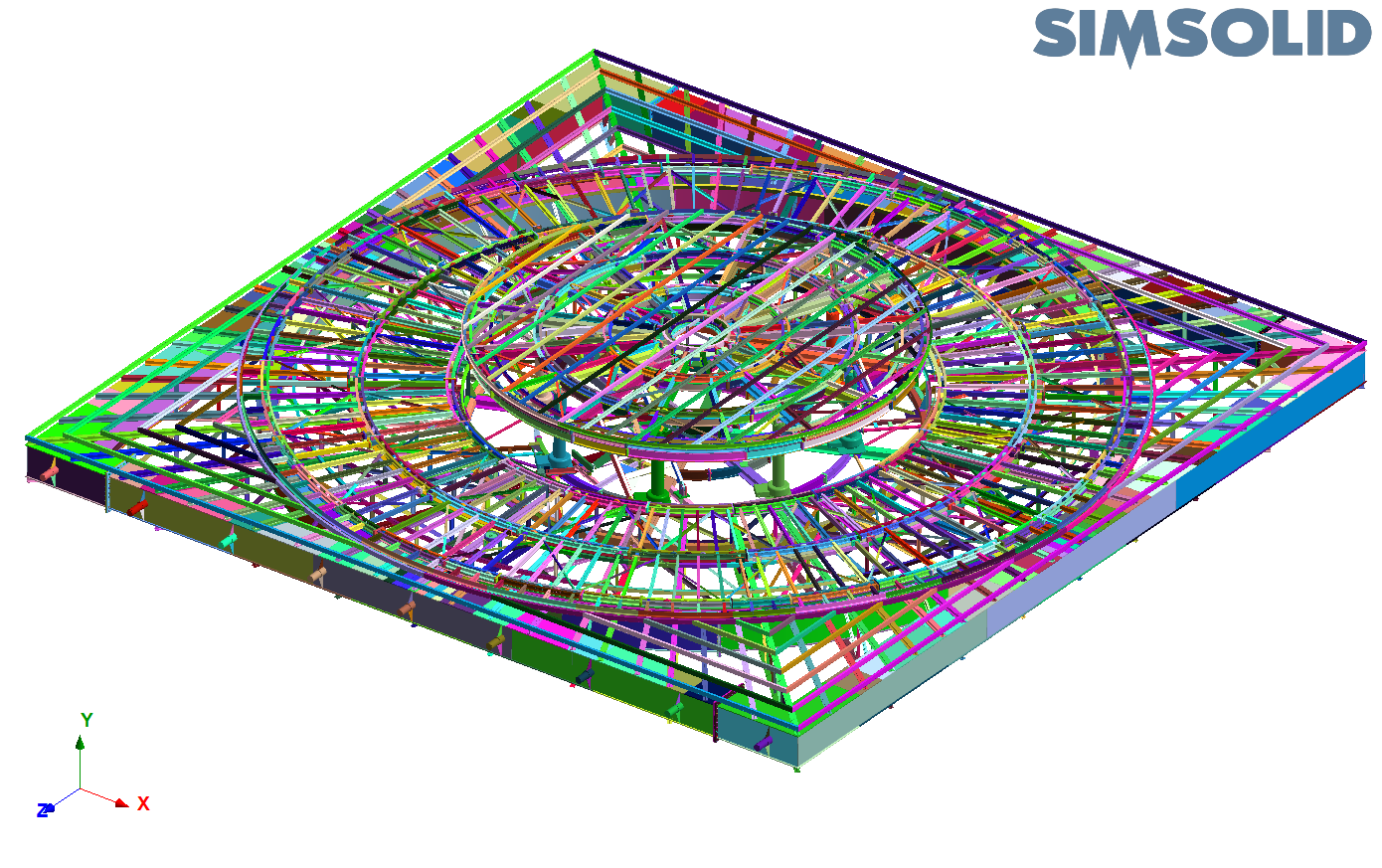
Rotating theater stage support framework, wood flooring removed
Large assembly workflow tools
The size and complexity of extremely large models, like this rotating stage, can make them a real challenge to visualize and process in conventional FEA systems. Altair SimSolid has several tools to make this easier. In the following, we highlight a few of them and provide examples of how they are used.Review parts tool
First, is the “Review parts” tool. Available from the Assembly workbench toolbar, the Review parts tool provides an easy way to sort your parts by Volume or Relative volume. Selecting a part (or group of parts) in the list will highlight their overall location on the model and a convenient zoom button is available when too much “surface clutter” is present. Parts can be suppressed or deleted directly from this menu making it a fast process to pare down the parts list to what is actually required for the analysis.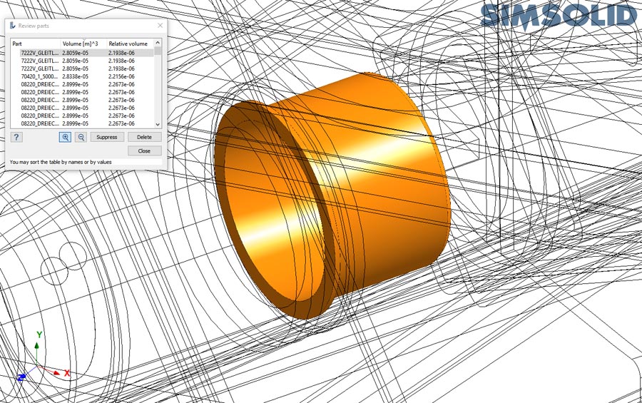
Review part tool – zoom to selected small part
Create connections tool
Once the part analysis set is defined, assembly connections must be determined. The “Set connections by proximity” is the first tool in the Connections workbench toolbar and one of Altair SimSolid’s most commonly used modeling features. This tool will automatically create connections for all parts in the model based on a simple set of high level parameters. Altair SimSolid is more tolerant than traditional FEA with respect to geometric mismatch between parts. Many people find this tool is all that is required to create assembly connections in a large complex model.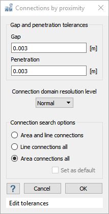
Show disconnected groups tool
The "Show disconnected group of parts” tool is available from the Connections workbench toolbar. It provides a ranked view (most to least) of connected part groups. For situations where connections cannot be found automatically, Altair SimSolid will display this dialog to help you diagnose the causes. Simply select each group name and all parts associated with it will be displayed as shown. Use the zoom button to locate hard to find parts and, if necessary, Suppress and/or Delete buttons are there to remove any problems.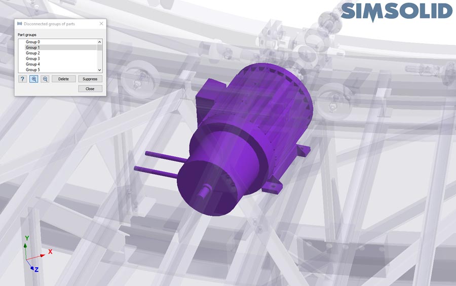
Dialog show disconnected groups of parts – Group 1 selected
Review part connections
Connections can be a real challenge to visualize in a large model with many thousands of parts. Altair SimSolid has a great method to sift through all the clutter. Connections for any single part can be easily viewed by right mouse button (RMB) selecting the part in the project tree or graphics area and selecting the “Review part connections” menu item. This will isolate the view to only show parts connected to the one selected, and will display a dialog to cycle through each connection. Options are available to edit any connection or contact conditions directly from this dialog.Connection missing? The "show not connected neighbor parts" checkbox can be used to toggle the display of adjacent parts. Find the one you want and pick the "Add new" button to manually create the missing connection.
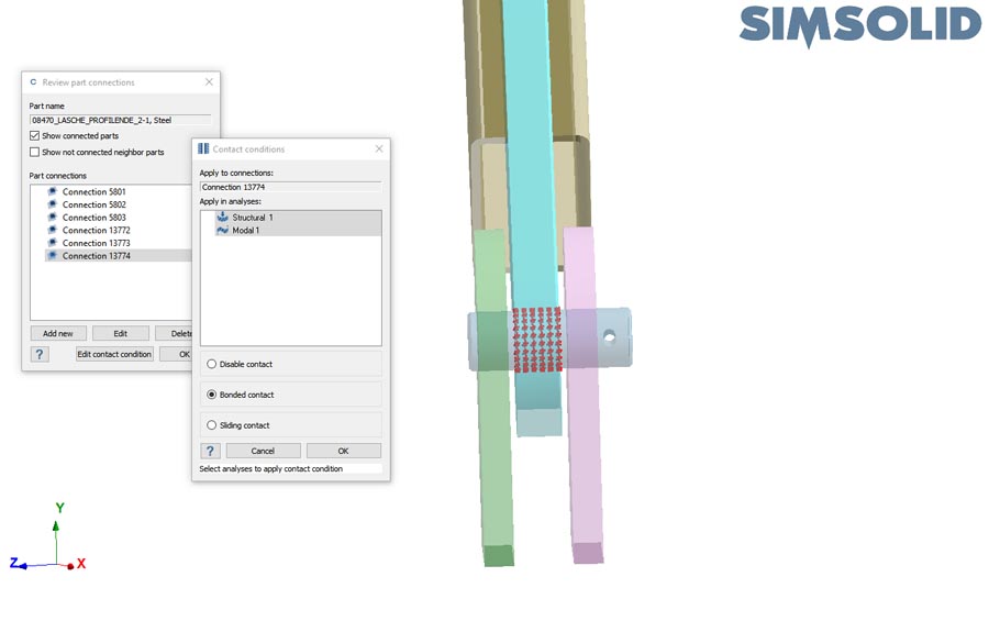
Review part connections – view limited to only connected parts, edit contact condition selected
Check rigid motions
After connections are complete, one final check is available to see if any rigid motions are present in the model. Rigid motions can arise from complex interactions between connections. For instance, from internal hinges (mechanism movements) or from overall rigid motion due to insufficient constraints. Rigid motions can be extremely difficult to diagnose and correct in most traditional FEA applications. Altair SimSolid's rigid motion check tool makes this much easier.
To get started, select the “Check rigid motions” button in the structural workbench toolbar. If any rigid motions are found, a displacement motion result is displayed that allows you to easily animate the parts that are insufficiently constrained. Select a motion and press the animate button. If necessary, exaggerate the deformation scale. The disconnected or weakly connected part movement will highlight where the problem is. For very complex assemblies, selecting the "Review moving parts" button will hide all other parts to help visualize where the problem are.
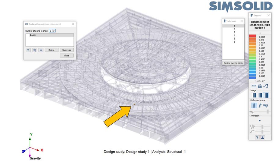
Check rigid motions – "Review moving parts" button is selected. Only parts with movement are shown.
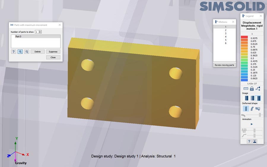
Check rigid motions – Zoom button selected. View zooms in to show Part 0 close up.
Rotating stage results
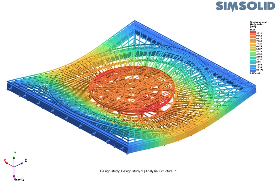
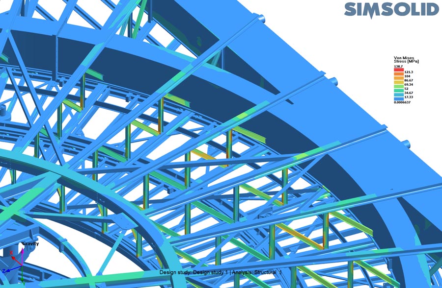
For our Rotating stage model, both static and modal analyses were performed. The static analysis contained side support posts, gravity and a dead load applied to the wooden floor. The modal analysis used the same post constraints and calculated the fundamental frequencies and mode shapes. All analyses were done on a Windows 10 based I-7 laptop with 16 GB of RAM. Altair SimSolid’s standard solution refinement with 3 adaptive solution passes was used.Here are a few results from the static analysis. Time required to solve was 11-1/2 minutes. Maximum memory used by Altair SimSolid was under 6 GB. Note that with Altair SimSolid, the word “solve” is equivalent to “Mesh + solved 3 times with adaptive mesh refinement” in traditional FEA context. A second run was made with Altair SimSolid Detailed solution refinement with 4 adaptive passes. The time required here was slightly longer, 21 minutes. Displacement and stress were comparable to the initial run.
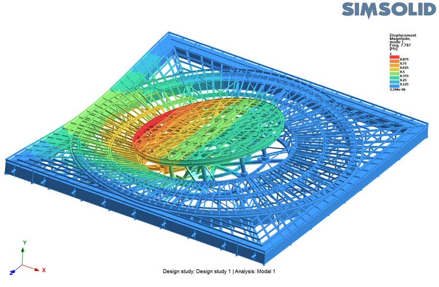
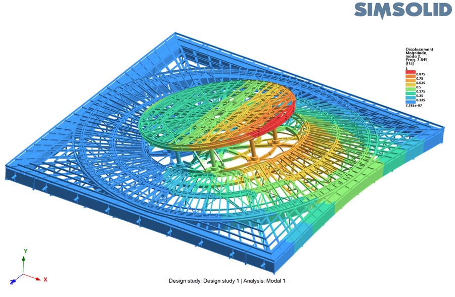
Finally, here are the first two constrained modes. Time required to solve was 22 minutes.
Managing complexity
Altair SimSolid is rapidly gaining the reputation as the best and most innovative structural solver available today. Being able to rapidly analyze large fully featured CAD assemblies on a standard desktop computer changes the way people use structural analysis tools. With Altair SimSolid, designers and engineers can rapidly assess structural performance during the design process where the impact of simulation is most beneficial. Analyzing full assemblies, more insight can be gained on the overall structural performance and design alternatives are easier to evaluate.Thinking about how analysis can help your design process? Consider Altair SimSolid.